USB Cable Replacement
Service Manual 10-25
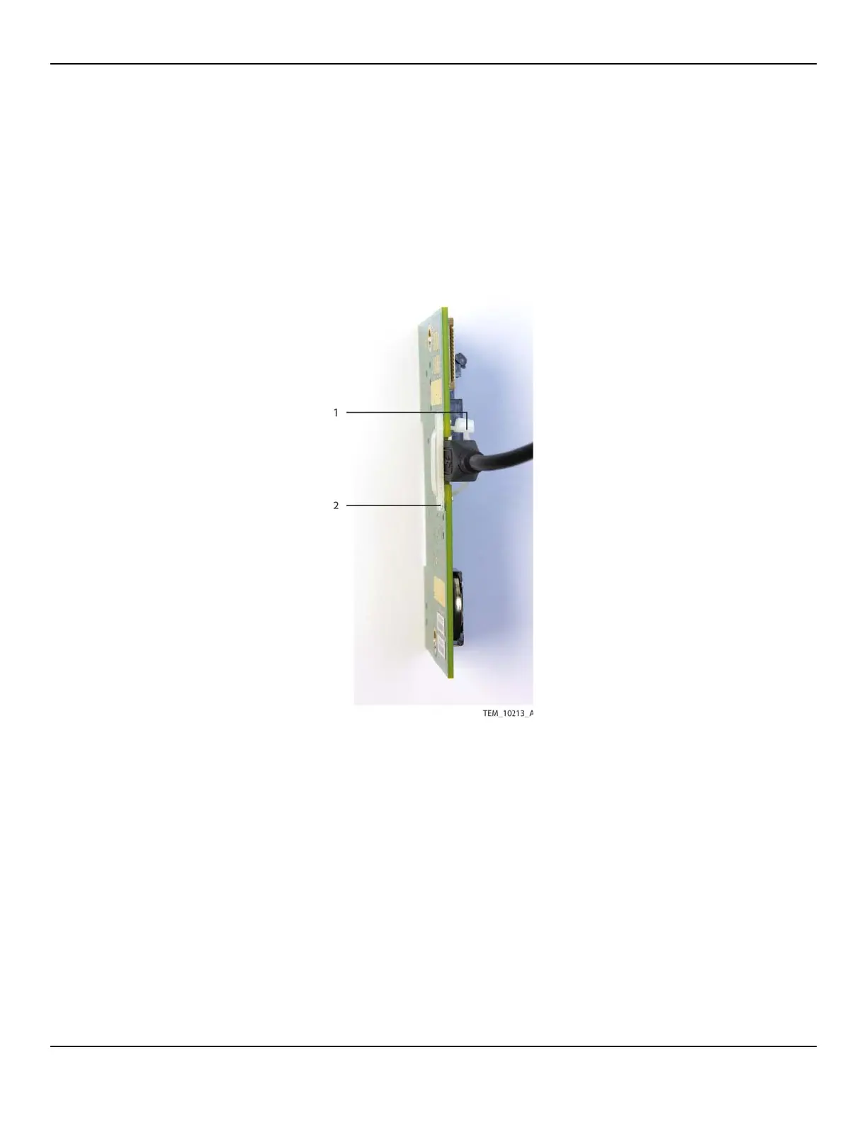
6. Detach the USB cable from the J203 connector as follows (Figure 10-20):
a. Cut the cable tie securing the USB cable.
b. Remove the cable tie and set the USB backing plate aside.
c. Disconnect the USB cable.
Figure10-20.USB Connection on UI PCBA
7. Attach the new USB cable to the UI PCBA as follows (Figure 10-21):
a. Place the backing plate against the non-component side of the PCBA, cover-
ing the notch at the top of the board. Align the holes in the backing plate with
the holes on each side of the notch.
b. From the front of the PCBA, insert the cable tie into either hole and through
the backing plate.
1 Cable Tie
2 Backing Plate