Thermistor Sensor Assembly Replacement
Service Manual 11-5
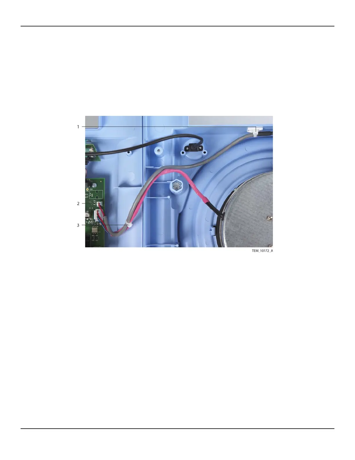
5. Carefully cut and remove the cable tie securing the thermistor cable to the fan
cable.
6. Disconnect the thermistor cable from the 2-pin P108 connector on the Power
PCBA. Remove the thermistor sensor assembly from the unit.
Figure11-3.Thermistor Cable Connections
7. Attach the new thermistor sensor assembly to the new rivet as follows (Figure 11-
4):
a. On the exposed twisted-pair wire of the assembly, measure a distance just
under 3 cm (approximately 1 and 1/8 inches) from the tip of the thermistor.
b. Wrap the wire once around the rivet as shown in Figure 11-4. The distance
from the base of the rivet head to the tip of the thermistor should measure
between 2.54 cm and 2.86 cm (between 1 inch and 1 and 1/8 inches).
1 Cable Tie and Tie Mount
(Thermistor Cable)
3 Cable Tie
(Thermistor Cable to Fan Cable)
2 P108 Connector
(Power PCBA)