Internal Component Replacement (Inside Front Enclosure)
10-44 Service Manual
To replace the power supply:
1. Follow the procedure Separating the Front and Rear Enclosures on page 9-2.
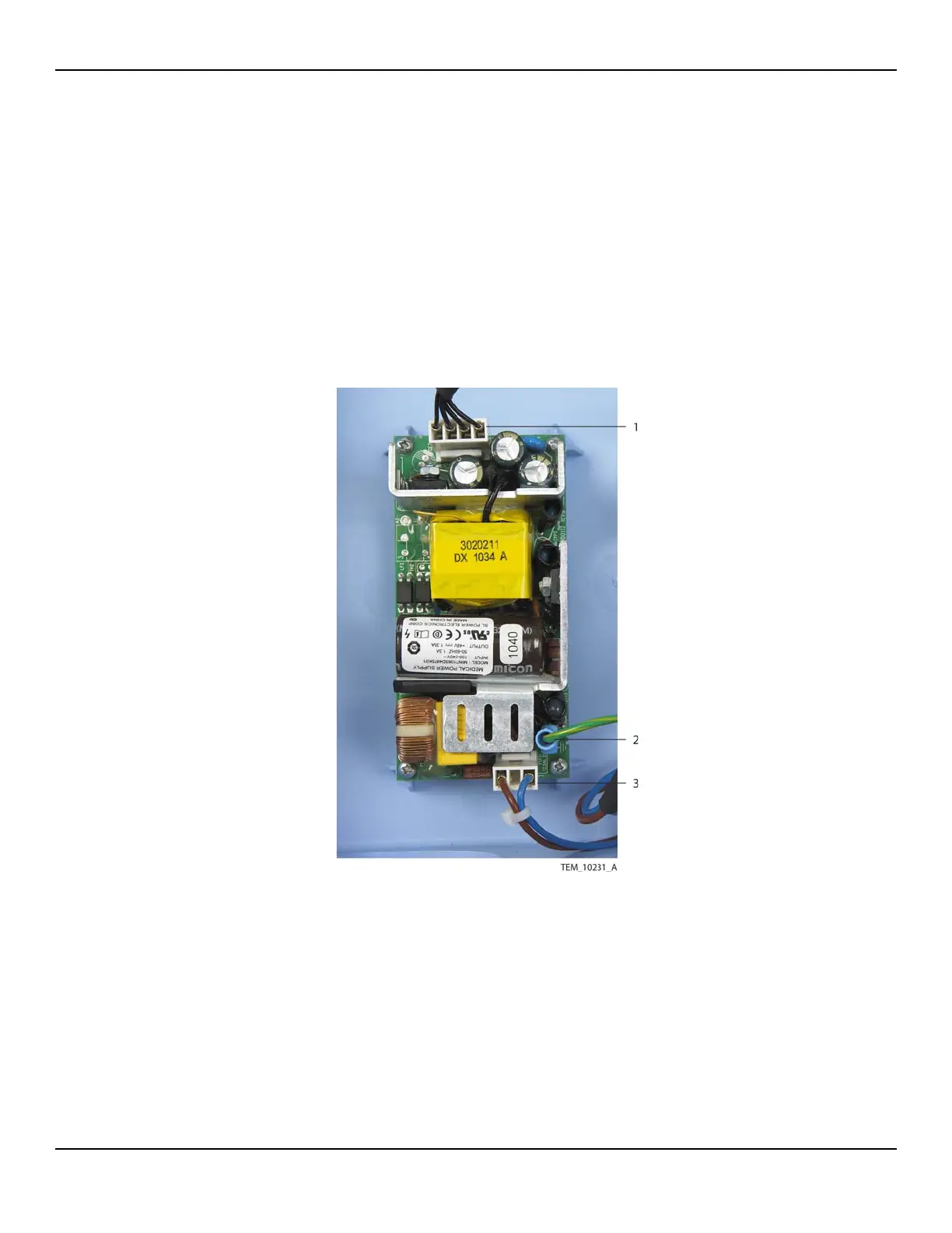
2. Disconnect the cables from the power supply as follows (Figure 10-32):
a. Disconnect the ground cable from the GND terminal.
b. Disconnect the AC power inlet wire assembly from the 3-pin CON1 connector.
c. Disconnect the power supply output cable from the 4-pin CON2 connector.
Figure10-32.Power Supply Connections
Note: A cable tie may secure the AC power inlet wire assembly to the power
supply mounting boss next to the CON1 connector. If so, cut and remove this
cable tie.
1 Power Supply Output Cable
(CON2 Connection)
3 AC Power Inlet Wire Assembly
(CON1 Connection)
2 Ground Cable
(GND Terminal Connection)