Display (LCD) Replacement
Service Manual 10-9
To replace the display:
1. Follow the procedure Separating the Front and Rear Enclosures on page 9-2.
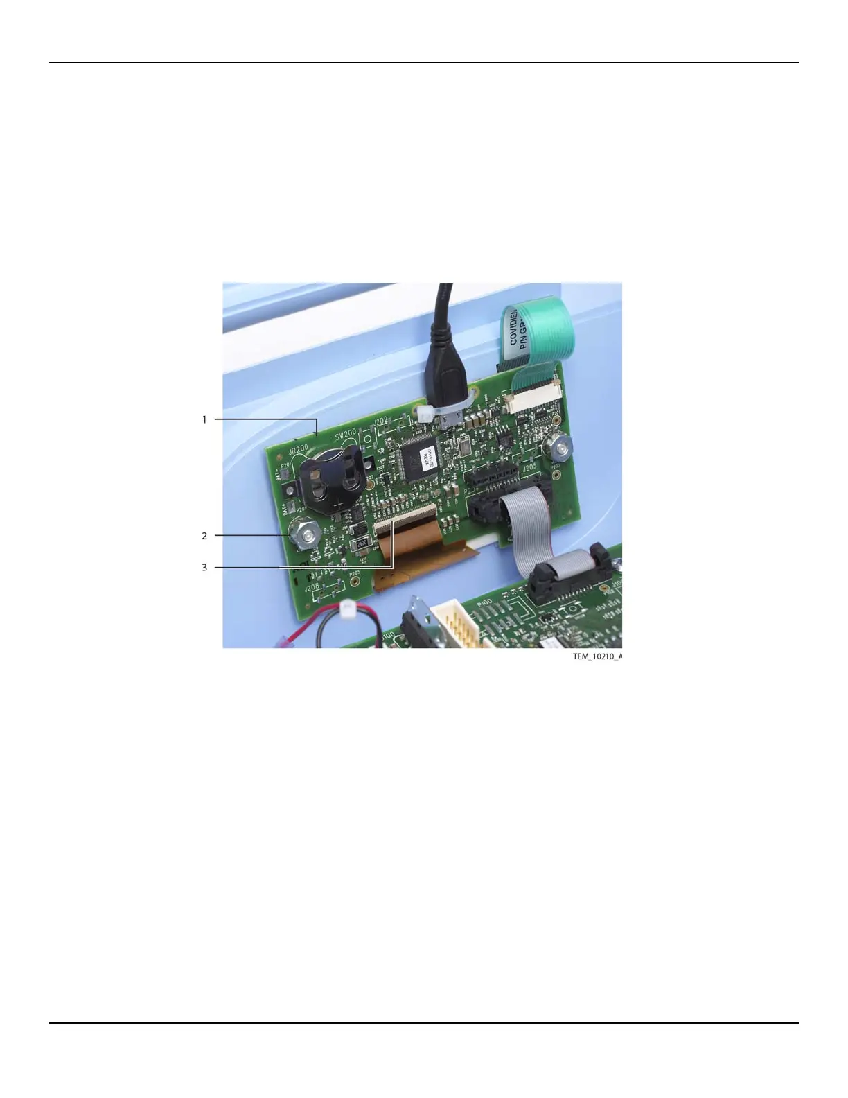
2. On the UI PCBA, lift the locking tab at the J207 connector, and disconnect the
display cable. Leave the remaining cables attached to the PCBA (Figure 10-8).
Figure10-8.Display Cable Connection on UI PCBA
3. Remove the UI PCBA from its mounting screws as follows:
a. Remove the nut from each mounting screw.
b. Remove the lock washer from each mounting screw.
c. Slide the UI PCBA off the mounting screws, taking care not to apply stress to
the cables still attached. Leave the shoulder washers in the mounting holes on
the PCBA.
1 UI PCBA 3 Display Cable
(J207 Connection)
2 Nut, Lock Washer,
Shoulder Washer (x2)