6
FUNCTIONS FOR TRANSMIT
6-15
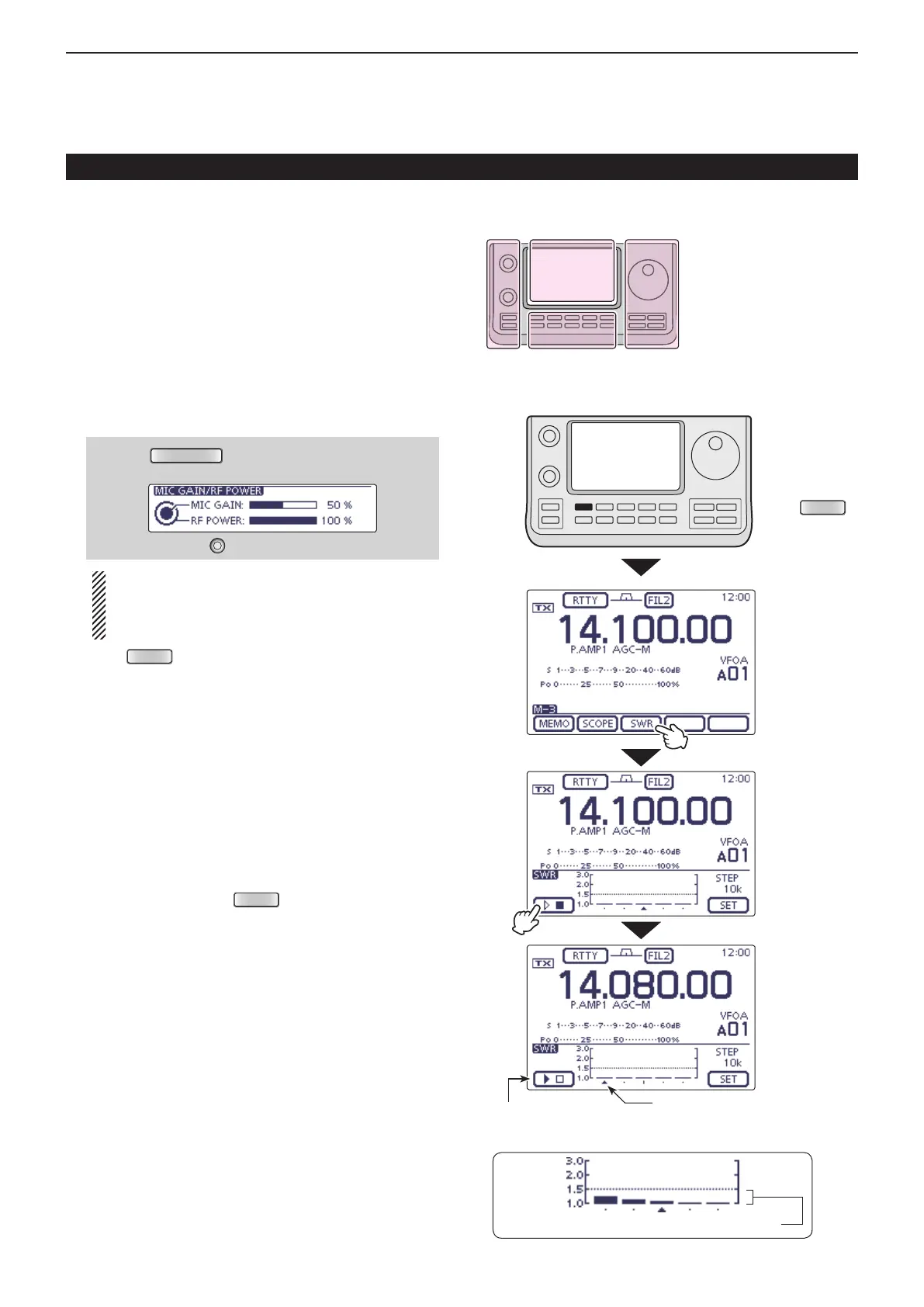
Measuring SWR
Plot measurement (Continued) D
Select the desired frequency band. (p. 3-6) q
On the Mode selection screen, select the RTTY or w
RTTY-R mode. (p. 3-17)
If necessary, adjust the RF power to more than 30 W e
on the Mic gain/RF power adjustment display.
• If your are operating in the 144 MHz band, adjust the RF
power to more than 20 W.
• If your are operating in the 430 MHz band, adjust the RF
power to more than 15 W.
• If your are operating in the 70 MHz band, adjust the RF
power to more than 20 W. (70 MHz band transmission is
available, depending on the transceiver version.)
q Push
(C) to open the MIC gain/RF
power adjustment display.
w Rotate [BANK] (L) to adjust the RF power.
Before transmitting, monitor the operating fre-
quency to make sure transmitting won’t cause
interference to other stations on the same fre-
quency.
Push r
(C) one or more times to select the
“M-3” screen (M-3 menu).
Touch [SWR]( t D) to display the “SWR” (SWR Graph)
screen.
Set the center frequency for the SWR to be mea- y
sured.
If necessary, touch [SET]( u D) to enter the “SWR
GRAPH SET” screen to set the Number of graph bar
or Measuring step.
• The selectable number of graph bar are 3, 5, 7, 9, 11 and
13.
• The selectable measuring steps are 10k, 50k, 100k and
500 kHz.
• Touch [](D) or push
(C) to return to the previ-
ous screen.
Touch [ i u](D) to start the measuring.
• A frequency marker, “∫,” appears below the left edge of
the graph bars and displays the frequency.
Hold down [PTT] on the microphone or switch ON o
the external TX switch to transmit.
• The bar graph displays the SWR.
!0 Release [PTT] or Switch OFF the external TX switch
to receive.
• The frequency marker moves to, and frequency display
changes to the next frequency to be measured.
!1 Repeat steps o and !0 to measure SWR over the
entire frequency range.
The L, R, C or D in the
instructions indicate the
part of the controller.
L: Left side
R: Right side
C: Center bottom
D:
Display (Touch screen)
Touch [SWR]
Touch [
]
Measuring SWR
While measuring SWR, the frequency cannot be changed
Frequency display mark
The best match is in this range. (1.5 or less)
Push

 Loading...


