1
PANEL DESCRIPTION
1-8
q TX ICON
Indicates either the displayed frequency can be
transmitted, or not.
➥ “ ” appears while the operating frequency is in
an amateur band.
➥ “ ” appears while the operating frequency is
not in an amateur band. However, when the “Band
Edge Beep” item is set to “OFF” in the “Function”
Set mode (p. 17-18), “ ” does not appear.
> Function > Band Edge Beep
“LMT” appears while the output power is de- ➥
creased because the Power FET’s temperature
is high.
“HOT” appears while transmission is inhibited be- ➥
cause the Power FET’s temperature is too high.
w MODE ICONS (p. 3-17)
Displays the selected operating mode. ➥
• “-D” appears when SSB data, AM data or FM data
mode is selected.
Touch to enter the Mode selection screen. ➥
• On the Mode selection screen, touch the block to se-
lect the operating mode.
e PASSBAND WIDTH ICON (pp. 5-5, 5-6)
Graphically displays the passband width for twin
PBT operation and the center frequency for IF shift
operation.
r TONE SQUELCH/DIGITAL SQUELCH ICONS
(Mode: FM)
➥“TONE” appears when the repeater tone function
is ON. (p. 4-25)
➥“TSQL” appears when the tone squelch function
is ON. (p. 4-22)
➥“DTCS” appears when the DTCS function is ON.
(p. 4-23)
(Mode: DV)
➥“DSQL” appears when the digital call sign squelch
function is ON. (p. 9-22)
➥“CSQL” appears when digital code squelch func-
tion is ON. (p. 9-22)
t IF FILTER ICON (p. 5-6)
Shows the selected IF filter. ➥
Touch to select one of three IF filter settings. ➥
• The selected lter passband width and shifting value
are displayed for 2 seconds in the window.
Touch for 1 second to display the “FILTER” screen ➥
to adjust the lter passband width.
➥
When the “FILTER” screen is displayed, touch for 1
second to return to the previous screen.
y QUICK TUNING ICON (p. 3-8)
Appears when the Quick tuning mode is selected.
• When “Z” is displayed, the frequency changes in preset
kHz or 1 MHz quick tuning steps.
• When “Z” is not displayed, the frequency changes in 10
Hz or 1 Hz steps.
u GPS ICON (p. 10-2)
➥ Appears when valid position data is received from
a GPS receiver that is connected to the [DATA1]
jack.
➥Blinks when invalid data is received from the GPS
receiver.
i SD CARD ICON
➥ “ ” appears when an SD card is inserted.
➥ “ ” and “ ” alternately blinks while accessing the
SD card.
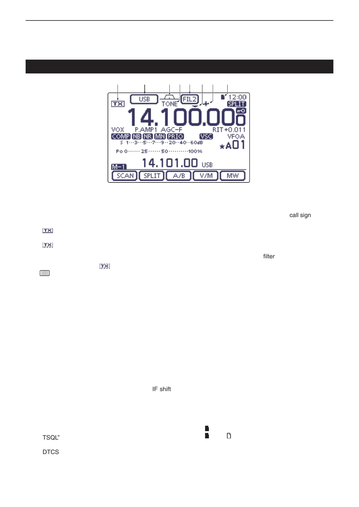
Controller — Function display
q w e tr iy u

 Loading...


