16
ANTENNA TUNER OPERATION
16-7
Setting the AT-180 internal switches
The optional AT-180 has 3 operating configurations for
HF band operation. Select a suitable configurations for
your antenna system.
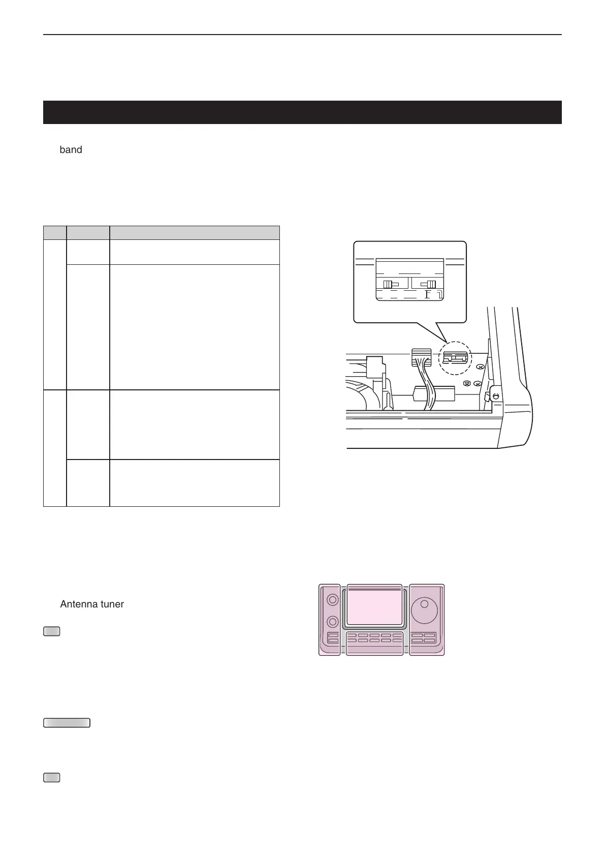
q Remove the top cover of the AT-180.
w Set the tuner switches to the desired positions ac-
cording to the table below.
D Automatic tuner start (HF bands only)
If you want to turn ON the tuner when the VSWR is
worth than 1.5:1, turn this function ON in the “Auto
Start” item of the “Function” Set mode, and turn OFF
the Antenna tuner.
(p. 17-20)
(C) > Function > Tuner > Auto Start
D PTT tune function
The AT-180 tunes when [PTT] is pushed after the
frequency is changed (more than 1%) if the AT-180
is turned ON. This function removes the ‘hold down
(L)’ operation and activates with the first
transmission on the new frequency. (p. 17-20)
Turn this function ON in the “PTT Start” item of the
“Function” Set mode.
(C) > Function > Tuner > PTT Start
SW Position Operation
S1
A
(default)
The tuner operating mode is set by S2
described below.
B THROUGH INHIBIT
The tuner tunes the antenna even when
the antenna has poor SWR (up to VSWR
3:1 after tuning). In this case, manual tun-
ing is necessary each time you change
the frequency although the tuner auto-
matically starts tuning when the VSWR
is higher than 3:1. This setting is called
“through inhibit,” however, the tuner is set
to “through” if the VSWR is higher than
3:1 after tuning.
S2
C TUNER SENSITIVE SETTING
The tuner tunes each time you transmit
(except SSB mode). Therefore, the low-
est SWR is obtained at any given time.
For SSB mode, the same SETTING as
the “D” position.
D
(default)
NORMAL
The tuner tunes when the SWR is higher
than 1.5:1. Therefore, the tuner activates
only when tuning is necessary.
• AT-180 inside top cover
The L, R, C or D in the
instructions indicate the
part of the controller.
L: Left side
R: Right side
C: Center bottom
D: Display (Touch screen)

 Loading...


