2
INSTALLATION AND CONNECTIONS
2-3
Antenna connection
For radio communications, the antenna is of critical im-
portance, along with output power and receiver sensi-
tivity. Select a well-matched 50 ø antenna and coaxial
cable feedline. We recommend 1.5:1 or better Voltage
Standing Wave Ratio (VSWR) on your operating bands.
The transmission line should be a coaxial cable.
When using a single antenna (for the HF, 50/70 MHz
bands), use the [ANT1] connector.
CAUTION: Protect your transceiver from lightning by
using a lightning arrestor.
Antenna SWR
Each antenna is tuned for a specified frequency
range, and the SWR usually increases outside the
range. When the SWR is higher than approximately
2.0:1, the transceiver automatically reduces the trans-
mit power to protect the final transistors. In that case,
an antenna tuner is useful to match the transceiver
and antenna. Low SWR allows full power for transmit-
ting. The IC-7100 has an SWR meter to continuously
monitor the antenna SWR.
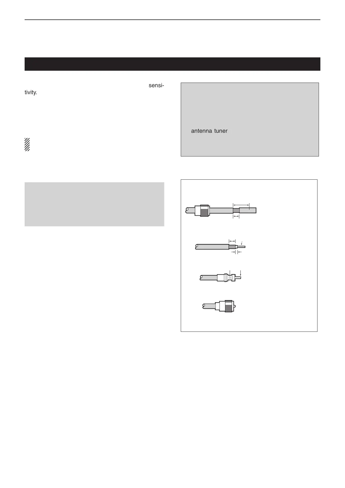
30 mm
10 mm (Tin)
10 mm
1–2 mm
solder solder
Tin
Coupling ring
PL-259 CONNECTOR INSTALLATION EXAMPLE
q
e
r
w
Slide the coupling ring
down. Strip the cable
jacket and tin the
shield.
Slide the connector
body on and solder it.
Screw the coupling
ring onto the connector
body.
Strip the cable as
shown at the left. Tin
the center conductor.
(30 mm
9
⁄8 in 10 mm
3
⁄8 in 1–2 mm
1
⁄16 in)
Antenna connection
Connect the cable from your HF, 50/70 MHz antenna
to the [ANT 1] connector.
Connect the cable from your 144/430 MHz antenna
to the [ANT 2] connector.

 Loading...


