1
PANEL DESCRIPTION
1-15
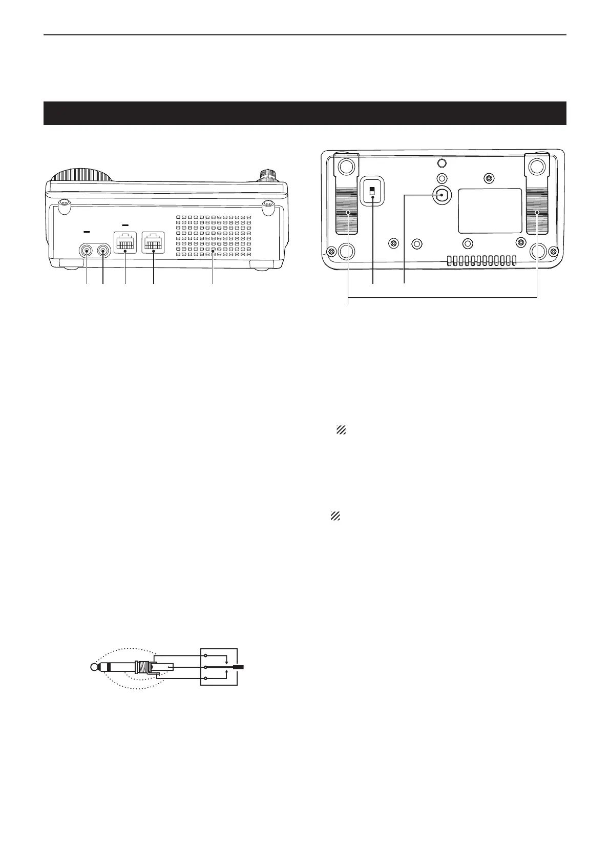
Controller — Rear and bottom panels
q HEADPHONE/SPEAKER JACK [PHONES/SP]
Plug in standard stereo headphones (impedance: 8
to 16 ø).
• Output power: More than 5 mW with an 8 ø load.
• When headphones are connected, the internal speaker,
and any external speaker, are disabled.
• When the [PHONES/SP] switch (y) on the bottom panel
is set to the SPEAKER position, an external speaker can
be used instead of headphones. This is convenient for
mobile or outdoor operation.
w ELECTRONIC KEYER JACK [ELEC-KEY]
Plug in a bug or paddle type key to use the internal
electronic keyer for CW operation. (p. 4-3)
• Set the keyer type to ELEC-KEY, BUG-KEY or Straight
key in the “Keyer Type” item of the “KEYER SET” mode.
• When a straight key is connected, “Straight key” must be
selected in the “Keyer Type” item of the “KEYER SET”
mode. (p. 4-10)
• A straight key jack is located on the rear panel. See [KEY]
on pages 1-17 and 2-6.
• You can reverse the keyer paddle polarity (dot and dash)
in
the “Paddle Polarity” item
of
the
“KEYER SET”
mode.
(p. 4-10)
• Four keyer memory channels are available for your con-
venience. (p. 4-10)
A standard 3.5(d) mm/
1
⁄8 inch plug
e MICROPHONE CONNECTOR [MIC]
Plug in the supplied or an optional microphone.
• See page 21-4 for appropriate microphones.
• See page 1-20 for microphone connector information.
• The optional OPC-589 cable can be used to connect an
8-pin microphone such as the SM-30 or SM-50.
• A microphone connector is also available on the Main
unit.
DO NOT simultaneously connect two microphones.
r MAIN UNIT CONNECTOR [MAIN UNIT]
Connects to the Main unit using with the supplied
OPC-2253 Control cable.
• The OPC-2253 Control cable is 3.5 meter (11.5 feet)
long.
DO NOT use any third party’s Ethernet cables.
t STAND
The length of the stand can be adjusted in two
steps.
• Adjust to the length not to incline back when you operate
the Front panel.
y PHONES/SPEAKER SWITCH [PHONE/SP]
Selects the [PHONES/SP] jack to connect a Head-
phones or external speaker.
u SCREW HOLE FOR STAND
Accepts the screw of a tripod stand. (Third party
product.)
q w e r
Speaker
t
uy

 Loading...


