2
INSTALLATION AND CONNECTIONS
2-9
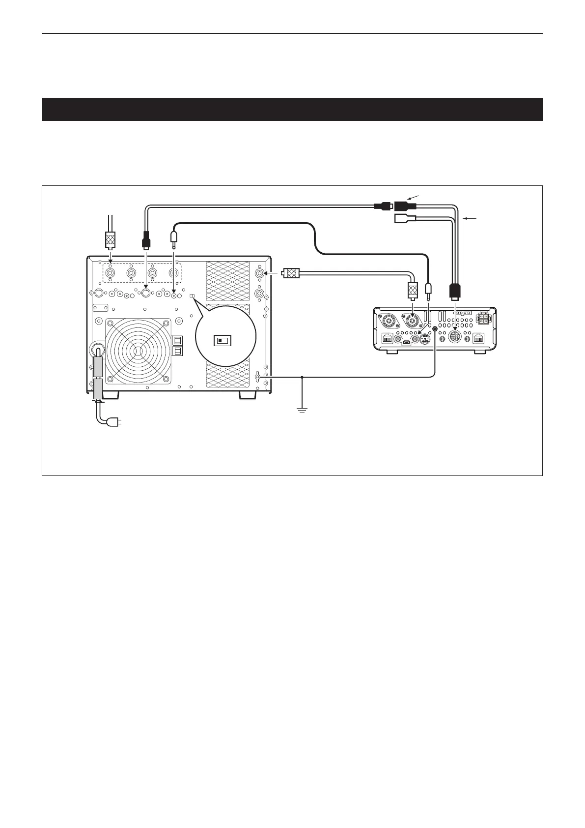
Remote Control
cable
ACC cable
To an antenna
[ACC-1]
[REMOTE][ANT]
IC-PW1/EURO
Non-European versions: 100–120 / 200–240 V
European version: 230 V
[INPUT1]
7-pin side
[REMOTE]
Coaxial cable
[ANT1]
IC-7100
OPC-599
conversion
cable
[ACC]
GND
GND
GND
Linear Amplier Connections
D Connecting the IC-PW1/EURO
To connect the Icom IC-PW1/EURO, see the diagram below.
For IC-PW1/EURO operation, refer to the amplifier’s instruction manual.
AC outlet

 Loading...


