EasyManuals Logo

Icom IC-7100 Advanced Instructions

Icom IC-7100
375 pages
To Next Page IconTo Next Page
To Previous Page IconTo Previous Page
Page #30 background imageLoading...
Page #30 background image
2
INSTALLATION AND CONNECTIONS
2-2
Select a location for the transceiver that allows ad-
equate air circulation, free from extreme heat, cold,
vibrations, away from TV sets, TV antenna elements,
radios and other electromagnetic sources.
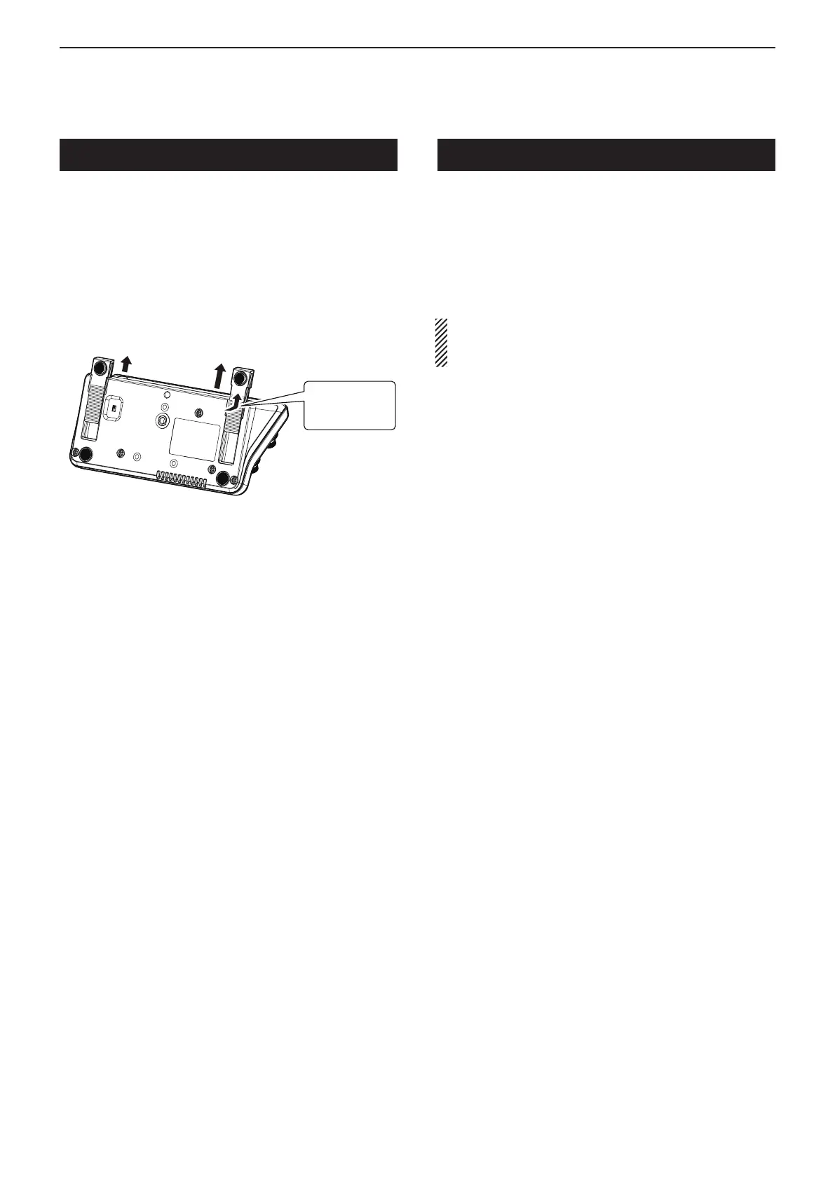
The base of the transceiver has adjustable feet for the
desktop use. Set the feet to one of two angles, to meet
your operating preference.
To prevent electrical shock, television interference
(TVI), broadcast interference (BCI) and other problems,
ground the transceiver using the GROUND terminal on
the rear panel.
For best results, connect a heavy gauge wire or strap
to a long ground rod. Make the distance between the
[GND] terminal and ground as short as possible.
R WARNING! NEVER connect the [GND] termi-
nal to a gas or electric pipe, since the connection
could cause an explosion or electric shock.
Slide in the
direction of
arrow.
Controller bottom view
Selecting a location Grounding
Previous view

Table of Contents

Other manuals for Icom IC-7100

Questions and Answers:

Question and Answer IconNeed help?

Do you have a question about the Icom IC-7100 and is the answer not in the manual?

Icom IC-7100 Specifications

General IconGeneral
Supply13.8 V DC ±15%
Voltage13.8 V DC
Operating Temperature-10°C to +60°C
Frequency Coverage0.030-199.999 MHz, 400-470 MHz
ModesSSB, CW, AM, FM, DV
Output PowerHF/50MHz: 100W, 144MHz: 50W, 430MHz: 35W
Receiver TypeSuperheterodyne
Antenna ConnectorSO-239 (HF/50MHz/144MHz), N-type (430MHz)
WeightMain unit: 2.3 kg
TypeBase/Mobile
Frequency Range TX1.8–54 MHz, 144–148 MHz, 430–450 MHz
Frequency Range RX0.030–199.999 MHz, 400–470 MHz
Memories505
Current ConsumptionTX: 22 A, RX: 1.2 A

Related product manuals