3
BASIC OPERATION
3-6
BAND REGISTER 1 REGISTER 2 REGISTER 3
1.8 MHz*
1
1.900000 MHz CW 1.910000 MHz CW 1.915000 MHz CW
3.5 MHz*
1
3.550000 MHz LSB 3.560000 MHz LSB 3.580000 MHz LSB
7 MHz 7.050000 MHz LSB 7.060000 MHz LSB 7.020000 MHz CW
10 MHz*
1
10.120000 MHz CW 10.130000 MHz CW 10.140000 MHz CW
14 MHz 14.100000 MHz USB 14.200000 MHz USB 14.050000 MHz CW
18 MHz 18.100000 MHz USB 18.130000 MHz USB 18.150000 MHz USB
21 MHz 21.200000 MHz USB 21.300000 MHz USB 21.050000 MHz CW
24 MHz 24.950000 MHz USB 24.980000 MHz USB 24.900000 MHz CW
28 MHz 28.500000 MHz USB 29.500000 MHz USB 28.100000 MHz CW
50 MHz*
1
50.100000 MHz USB 50.200000 MHz USB 51.000000 MHz FM
144 MHz
145.000000 MHz FM 145.100000 MHz FM 145.200000 MHz FM
430 MHz*
1
433.000000 MHz FM 433.100000 MHz FM 433.200000 MHz FM
General*
1, 2
15.000000 MHz USB 15.100000 MHz USB 15.200000 MHz USB
*
1
The default frequency and mode settings differ depending on the version. Above list shows the USA version’s.
*
2
[GENE] selects the general coverage band.
D Using the band stacking registers
The triple band stacking register provides 3 memories
for each band key to store frequencies and operating
modes.
This function is convenient when you operate 3 operat-
ing modes on one frequency band.
For example, one register can be used for a CW fre-
quency, another for an SSB frequency and the other
one for an RTTY frequency.
If a band key or [GENE] is touched for 1 second once,
the last used frequency and operating mode are called
up. When the key is touched for 1 second again, anoth-
er stored frequency and operating mode are called up.
See the table below for a list of the available frequency
bands and their default frequency and mode settings.
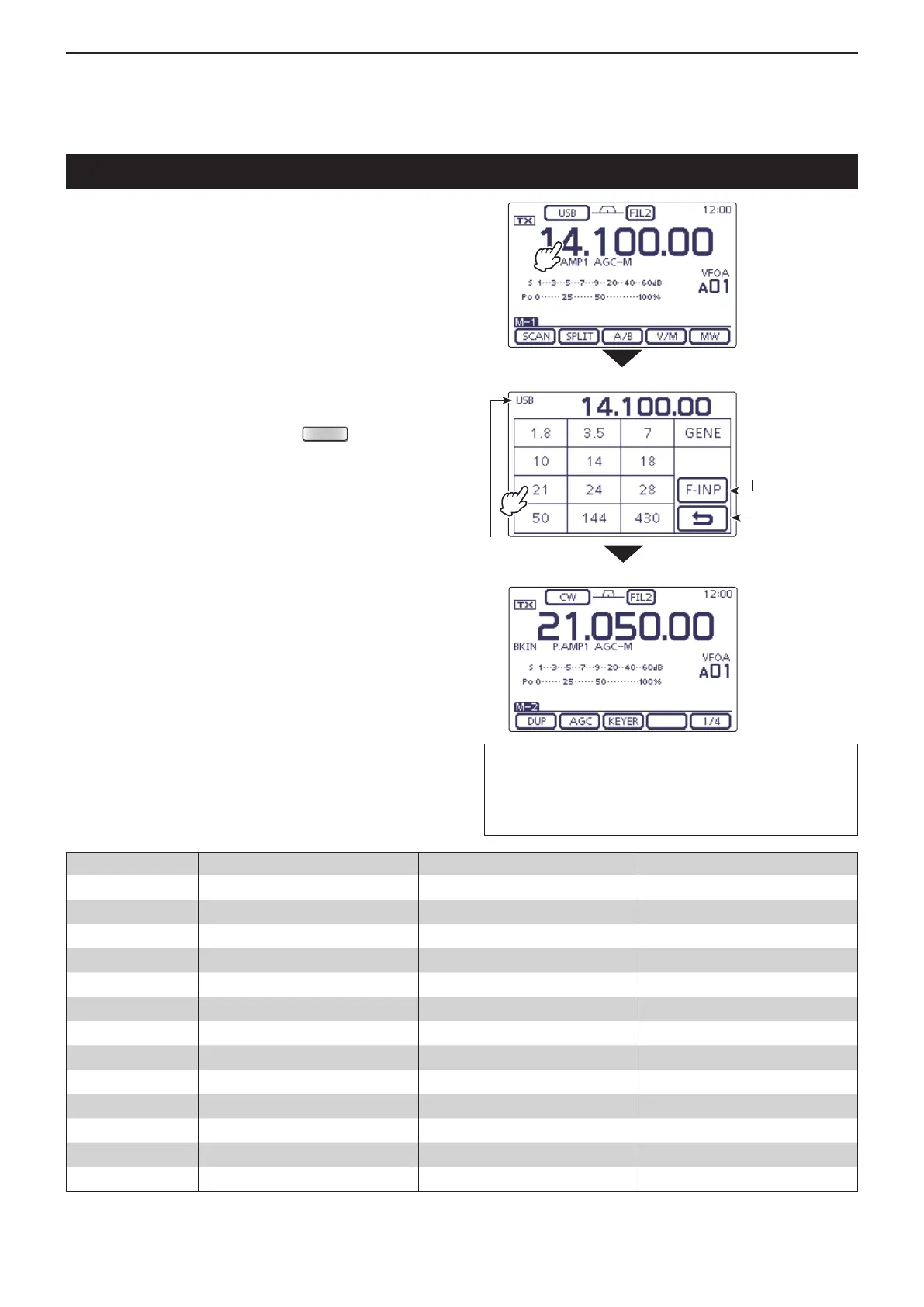
Select the frequency band you want to use.
Touch the MHz digits of the frequency readout to en- q
ter the Band selection screen.
Touch a desired operating band, “1.8” to “430” or w
“GENE.”
• After touching the band, the display moves to the se-
lected band, and returns to the frequency display.
• Touch a band for 1 second to select the Band stacking
register, Register 1, Register 2 or Register 3 on the Band
selection screen.
• Touch [F-INP] to enter the Direct input screen. (p. 3-11)
• If desired, touch [](D) or push
(C) to exit the
screen.
Selecting a frequency band
The L, R, C or D in the instructions indicate the
part of the controller.
L: Left side, R: Right side, C: Center bottom
D: Display (Touch screen)
• Band selection screen
Enters the Direct
input screen
Example: Touch “21” in the above screen
Cancel edit
Operating mode
Touch the MHz
digits.

 Loading...


