1
PANEL DESCRIPTION
1-17
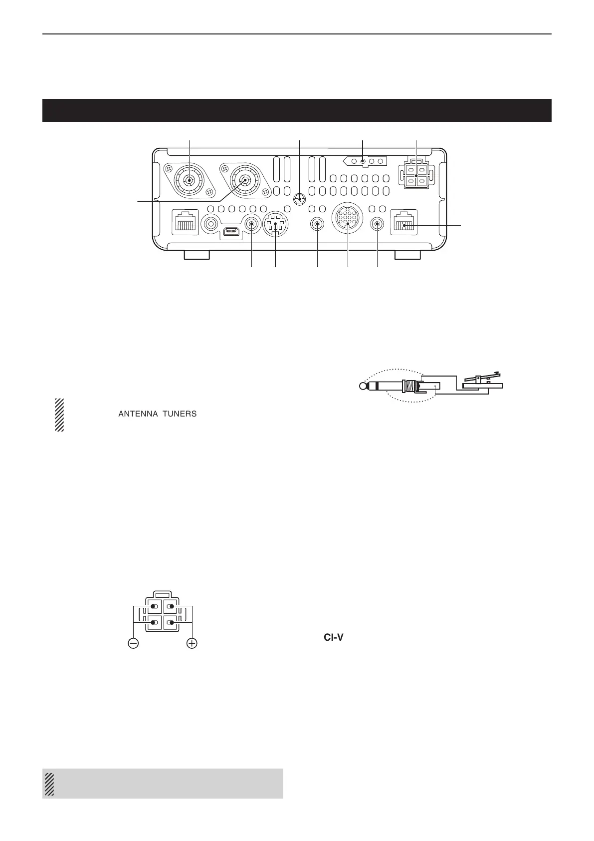
Main unit — Rear panel
q ANTENNA CONNECTOR 1 [ANT1]
w ANTENNA CONNECTOR 2 [ANT2] (p. 2-3)
Connect a 50 ø antenna with a PL-259 plug con-
nector.
• [ANT1] is used for the HF, 50/70 MHz frequency bands.
• [ANT2] is used for the 144/430 MHz frequency bands.
• [ANT1] is used below 74.8 MHz, and [ANT2] is used for
74.8 MHz or above.
When using an optional AH-4 or AT-180 h f /50 m h z
a u t o m a t i c a n t e n n a t u n e r s , connect it to the
[ANT1] connector.
e GROUND TERMINAL [GND] (p. 2-2)
Connect this terminal to ground to prevent electrical
shocks, TVI, BCI and other problems.
r TUNER CONTROL SOCKET [TUNER] (p. 2-7)
Connect the control cable from an optional AH-4 h f /
50 m h z a u t o m a t i c a n t e n n a t u n e r .
t DC POWER SOCKET [DC 13.8V] (p. 2-8)
Connect 13.8 V DC through the supplied DC power
cable.
y CONTROLLER CONNECTOR [CONTROLLER]
Connects to the Controller using with the supplied
OPC-2253 Control cable.
• The OPC-2253 Control cable is 3.5 meter (11.5 feet)
length.
• DO NOT use any third party’s Ethernet cables.
u STRAIGHT KEY JACK [KEY] (p. 2-6)
Connect a straight key or external electronic keyer
using a standard 3.5(d) mm/
1
⁄8 inch plug.
• To use the internal electronic keyer for CW operation,
connect to [ELEC-KEY] on the Rear panel of the Con-
troller. (p. 1-15)
i ACCESSORY SOCKET [ACC]
Connect control lines for external equipment such
as a linear amplifier, an automatic antenna selector/
tuner, a TNC for data communications, and so on.
• See page 1-19 for socket information.
o DATA1 JACK [DATA1] (p. 2-7)
➥ Connect a PC through the optional OPC-1529R
d a t a c o m m u n i c at i o n c a b l e , for low-speed data
communication in the DV mode. (p. 9-17)
➥ Connect a GPS receiver through the optional
OPC-1529R d a t a c o m m u n i c a t i o n c a b l e , for GPS
operation. (p. 10-2)
!0 DATA2 SOCKET [DATA2] (p. 2-7)
Connect a TNC (Terminal Node Controller), and so
on, for high speed data communications.
!1 CI-V REMOTE CONTROL JACK [REMOTE]
(p. 2-7)
➥ Connect
a PC, using the optional CT-17 c i -v l e v e l
c o n v e r t e r , for external control of the transceiver.
➥ Use for the transceive function with another Icom
CI-V transceiver or receiver.
When the transceive function is set to ON, chang-
ing the frequency, operating mode and so on, on
the IC-7100 automatically changes those settings
on other Icom transceivers or receivers, and vice
versa.
➥ Connect another IC-7100, using a mini plug
cable*, for transceiver to transceiver cloning.
* Purchase separately
While cloning using the CS-7100 software, DO NOT
connect anything to the [REMOTE] jack.
q
w e r t
y
uio!0
!1

 Loading...


