1
PANEL DESCRIPTION
1-18
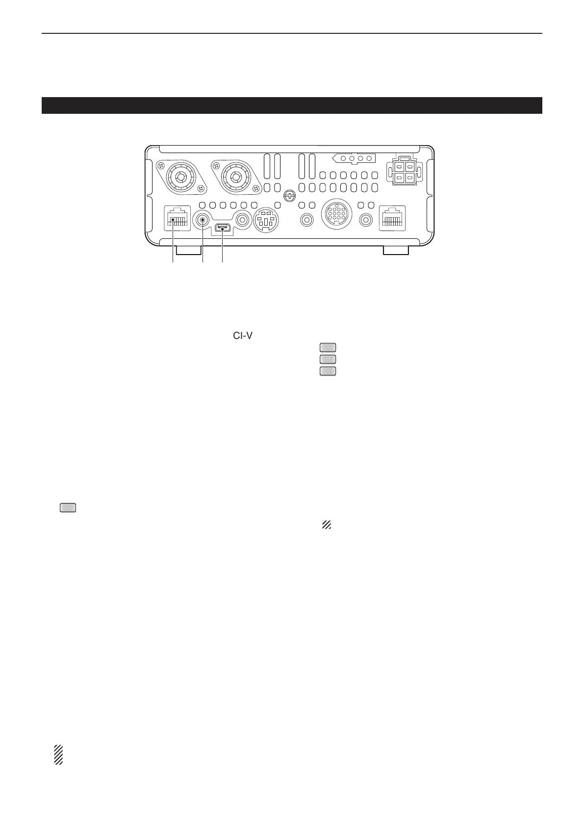
!2 USB (Universal Serial Bus) PORT
[USB]
Using a USB cable, connect a PC to do the follow-
ing:
- Input modulation
- Remotely control the transceiver using CI-V com-
mands (p. 20-2)
- Send the received audio to the PC
-
Send the decoded characters to the PC
- Low-speed data communication in the DV mode (p.
9-17)
- Cloning using the optional CS-7100 c l o n i n g s o f t -
w a r e (p. 21-5)
- Remote control operation using the optional RS-
BA1 ip r e m o t e c o n t r o l s o f t w a r e (p. 21-5)
• Two COM port numbers are assigned to the [USB] con-
nector. One of them is “USB1,” used for cloning and CI-V
operation. The other one is “USB2,” whose function is se-
lected in “USB2 Function” item of the “Connectors” Set
mode. (p. 17-25)
> Connectors > USB2/DATA1 Function >
USB2 Function
About the USB driver:
The USB driver and the installation guide can be
downloaded from our website.
➥ http://www.icom.co.jp/world/index.html
The following items are required:
PC
• Microsoft
®
Windows
®
XP,
Microsoft
®
Windows Vista
®
,
Microsoft
®
Windows
®
7 or
Microsoft
®
Windows
®
8 OS
• A USB 1.1 or 2.0 port
Other items
• USB cable (supplied with the transceiver)
• PC software (such as the optional RS-BA1 or CS-
7100)
NEVER connect the transceiver to a PC until the
USB driver installation has been completed.
About the modulation input:
Select “USB” in the “Connectors” Set mode item
“DATA OFF MOD” or “DATA MOD.” The modulation
input level from the USB jack can be set in the Set
mode item “USB MOD Level.” (p. 17-24)
> Connectors > DATA OFF MOD
> Connectors > DATA MOD
> Connectors > USB MOD Level
!3
EXTERNAL SPEAKER JACK [SP]
Connect to an external speaker (4 to 8 ø).
!4 MICROPHONE CONNECTOR [MIC]
Plug in the supplied or an optional microphone.
• See page 21-4 for appropriate microphones.
• See page 1-20 for microphone connector information.
• The optional OPC-589 cable can be used to connect an
8-pin microphone such as the SM-30 or SM-50.
• A microphone connector is also available on the Control-
ler.
DO NOT simultaneously connect two microphones.
Main unit — Rear panel (Continued)
!2!3!4
 Loading...


