2
INSTALLATION AND CONNECTIONS
2-10
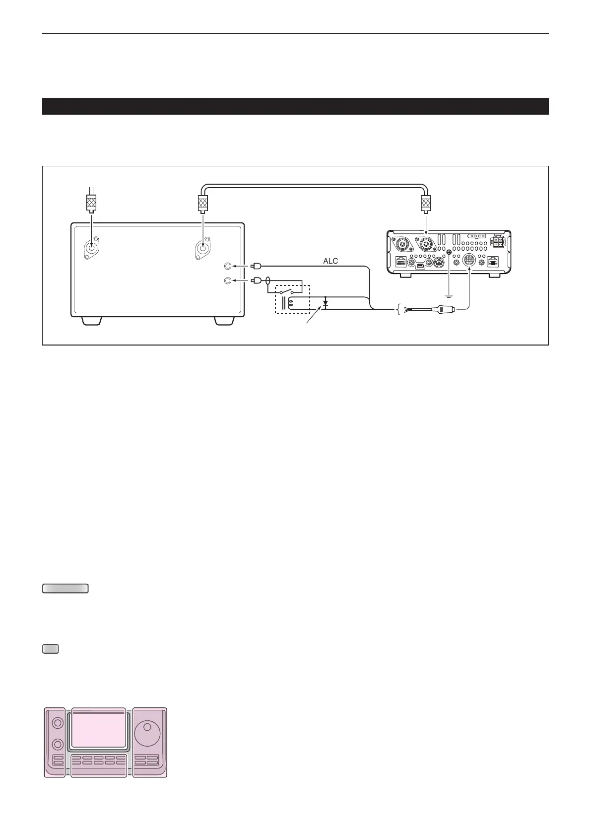
D Connecting a non-Icom linear amplier
GND
HSEND
(Orange)
/VSEND
ALC (Blue)
13.8 V (Gray)
Relay
RF INRF OUT
ALC
SEND
Non-Icom Linear amplifier
To an antenna
[ANT1]*
2
13-pin plug with ACC cable
Switching diode
ACC
IC-7100
To connect a non-Icom HF, 50/70*
1
MHz bands linear amplifier, see the diagram below.
*
1
70 MHz band transmission is available, depending on the transceiver version.
RWARNING!
The SEND terminal of the linear amplifier must be connected to the HSEND (ACC connector pin 3) for the HF, 50/70*
MHz bands, and to VSEND (ACC connector pin 7) for the 144/430 MHz bands. An external relay must be used.
* 70 MHz band transmission is available, depending on the transceiver version.
When the HSEND (or VSEND) terminal controls the inductive load (such as a relay), a counter-electromotive force
can damage or cause the transceiver to malfunction. To prevent this, add a switching diode on the load side of the
circuit to the counter-electromotive force absorption.
•
We recommend adding a switching diode, such as an “1SS133”.
•
When the diode is added, a switching delay of the relay may occur. Be sure to check its switching action before
operating.
The ALC input level must be in the range 0 V to –4 V. The transceiver does not accept positive voltage. Non-matched
ALC and RF power settings could cause a fire or damage the linear amplifier.
When using a linear amplier such as IC-PW1/EURO, adjust the output power to stay within the ALC zone by pushing
(C). For ALC zone information, refer to ‘Basic transmit operation.’ (p. 3-23)
When using a linear amplifier that has a time delay between receiving and transmitting, a high SWR might cause the
linear amplifier to malfunction. To prevent this, slow the TX Delay the “TX Delay” settings in the “Function” Set mode.
(p. 17-19)
(C) > Function > TX Delay
Linear Amplifier Connections (Continued)
*
2
When connecting a 144 MHz or 430 MHz band's liner am-
plifier, connect to [ANT2].
The L, R, C or D in the
instructions indicate the
part of the controller.
L: Left side
R: Right side
C: Center bottom
D:
Display (Touch screen)

 Loading...


