2
INSTALLATION AND CONNECTIONS
2-7
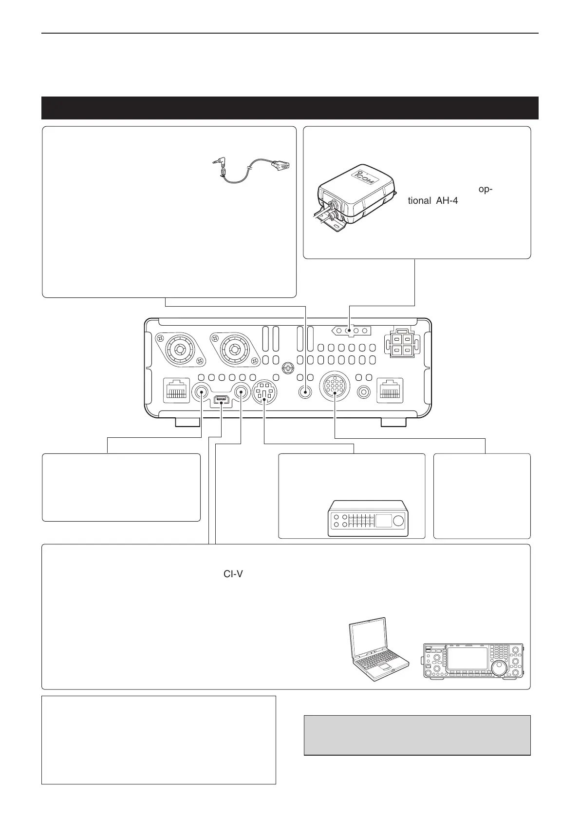
[DATA1] DATA1 JACK
For GPS operation (p. 10-2)
• Connect a GPS receiver to the transceiv-
er.
• The optional OPC-1529R (Data commu-
nication cable) and a 3rd party's GPS re-
ceiver with RS-232C Port are required.
For low-speed data communication in the DV mode (p. 9-17)
• Connect the transceiver to a PC.
• The USB cable can also be used for low-speed data commu-
nication..
[TUNER] TUNER CONTROL SOCKET (p. 16-1)
Connect the control
cable from an op-
tional AH-4 (HF/50
MHz automatic an-
tenna tuner).
AH-4 (Optional)
[SP] (EXTERNAL) SPEAKER JACK
(p. 2-5)
Similar to the [PHONES/SP] jack
on the controller. Plug in an exter-
nal speaker. 3.5(d) mm/
1
⁄8˝ plug
[USB] USB (Universal Serial Bus) PORT
•
Remotely control the transceiver using CI-V commands
(p. 20-2)
•
Send the received audio to the PC
•
Input modulation (pp. 1-18, 17-8)
•
Send the decoded RTTY outputs to the PC
• Low-speed data communication in the DV mode
(p. 9-17)
•
Cloning using the optional CS-7100 c l o n i n g s o f t w a r e
(p. 19-5)
•
Remotely control using the optional RS-BA1
[DATA2]
DATA2 SOCKET (p. 18-2)
Connect a TNC (Terminal Node Con-
troller) for packet communication.
[ACC] ACCESSORY
SOCKET (p. 1-19)
Connect control lines
for external equipment
such as TNC or a PC.
NOTE: By setting “ACC/USB output selection” of the
Connectors Set mode (p. 17-24), the receiving tone
can normally be output from the [ACC] socket, and
the [USB] port can output an IF signal (12 kHz). This
is required for the Software-Defined Radio (SDR) op-
eration. The Digital Radio Mondiale (DRM) broadcast
can be received using SDR.
CAUTION: DO NOT connect any device to [RE-
MOTE] when cloning using the optional CS-7100
c l o n i n g s o f t w a r e .
The External Units Connections to a Transceiver
[REMOTE] REMOTE CONTROL JACK
•
Remotely control the transceiver using CI-V commands.
(p. 20-2)
•
Cloning between transceivers (p. 19-5)
3.5(d) mm/
1
⁄8˝ plug

 Loading...


