12
SCAN OPERATION
12-8
A programmed scan searches for signals between Pro-
gram Scan Edge channels “1A–3A” and “1B–3B.”
Before starting the programmed scan, scan edges must
be programmed into these channels.
See the previous page for scan edge programming.
If the same frequencies are programmed into the
Program Scan Edge channels, the programmed
scan will not start.
Touch the Memory channel number indication once q
or twice to select the VFO mode. (p. 3-4)
Touch the mode icon to display the Mode selection w
screen, and then touch the desired operating mode.
• The operating mode can also be changed while scan-
ning.
Touch the frequency ‘kHz’ area on the display for 1 e
second to display the Tuning step selection screen,
and then touch the desired tuning step. (p. 3-9)
• The tuning step can also be changed while scanning.
Push r
(C) one or more times to select the “M-
1” (Menu 1) screen.
t
Touch
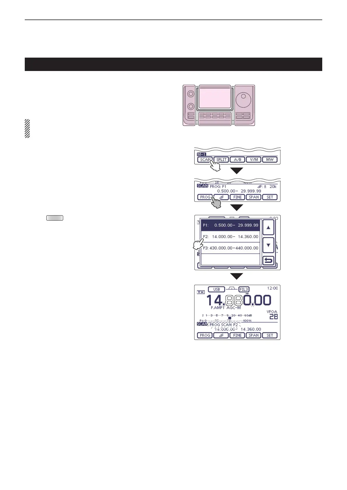
[SCAN](D) to display the “SCAN” screen.
Touch [PROG]( y D) for 1 second, and then touch the
desired scan range between “P1,” “P2” and “P3.”
• The scan searches between programmed scan channels
1A–1B (P1), 2A–2B (P2) or 3A–3B (P3).
• Example: P2: 14.000.00–14.360.00
Touch [PROG]( u D) to start the programmed scan.
• The MHz and kHz decimal points, and the selected scan
range display blink while scanning.
• If
“Up/Down” is selected as
the “MAIN DIAL (SCAN)” op-
tion
in the Scan Set mode, rotating the Dial changes the
scanning direction. (p. 12-5)
When the scan detects a signal, the scan stops, i
pauses or ignores it, depending on the Scan Resume
function, the VSC function or the squelch status.
Push [PROG]( o D) to cancel the scan.
While Programmed scanning
Touch
[SCAN]
Touch [PROG]
for 1 second.
Touch the
desired scan
range
(Example: P2)
Programmed scan (VFO mode)
The L, R, C or D in the
instructions indicate the
part of the controller.
L: Left side
R: Right side
C: Center bottom
D: Display (Touch screen)

 Loading...


