1
PANEL DESCRIPTION
1-22
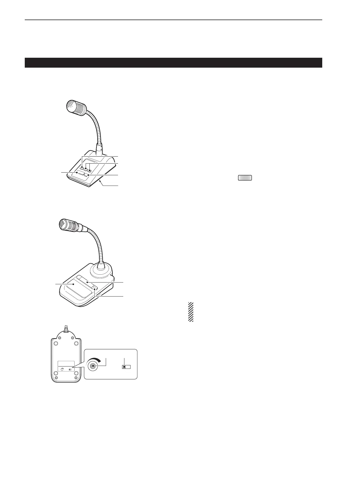
Microphone (Continued)
q PTT SWITCH
Hold down to transmit, release to receive.
w PTT LOCK SWITCH
Push to lock the PTT switch in the transmit mode.
e UP/DOWN SWITCHES [UP]/[DN]
Change the selected readout frequency or memory
channel.
• Holding down continuously changes the frequency or
memory channel number.
• While holding down
, the transmit readout frequen-
cy can be controlled while in the split frequency mode.
• The [UP]/[DN] switch can simulate a key paddle. Preset in
the “KEYER SET” mode (U/D KEY; MIC Up/Down Keyer).
(p. 4-10)
r LOW CUT SWITCH
Push (SM-50)/Slide (SM-30) to cut out the low fre-
quency components of input voice signals.
t PTT LOCK INDICATOR [LOCK]
(Only for the SM-30)
Lights red when the PTT lock switch (w) is ON.
y MIC GAIN VOLUME [MIC GAIN]
Rotate to adjust the microphone output level.
• Use this control as an addition to the microphone gain
setting of the connected transceiver.
Rotating the control too far clockwise may result
in an output level that is too high and transmit sig-
nal distortion.
D SM-50 (Option)
D SM-30 (Option)
TOP VIEW
BOTTOM VIEW
The optional OPC-589 cable is required to connect these 8-pin microphones.

 Loading...


