3
BASIC OPERATION
3-12
Setting frequency (Continued)
Direct frequency input (Continued) D
• Split offset frequency input
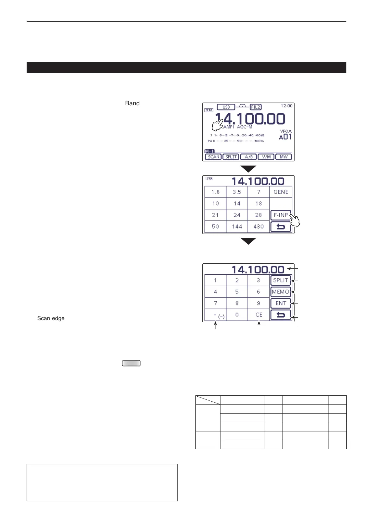
Touch the MHz digits to enter the Band selection dis- q
play.
Touch [F-INP]( w D) to enter the Direct input screen.
If the Shift direction is minus, touch “• (–).” e
• [SPLIT] changes to [–SPLIT], and displays the Minus set-
ting mode.
Touch the desired number to enter the desired fre- r
quency shift.
• –9.999 to +9.999 MHz can be set in 1 kHz steps.
Touch [SPLIT] or [–SPLIT]( t D) to input the frequency
shift to the transmit frequency, and the Split function
is turned ON.
[Example]
To transmit on a 10 kHz higher frequency:
Touch [1], [0] then [SPLIT]. ➥
To transmit on 1.025 MHz lower frequency:
Touch [• (–)], [1], [0], [2], [5] then [–SPLIT]. ➥
• Memory channel selection
Open the Direct input screen. q
Touch the desired memory channel number. w
• Selectable memory channels are 1 to 99 in the selected
memory bank A to E.
The memory channels in the other memory banks cannot
be selected.
• Scan edge channels and Call channels can also be se-
lected. (Shown in the table to the right below.)
Touch [MEMO]( e D) to select the channel.
• The selected memory channel is displayed, and then exit
the Direct input screen.
• If desired, touch “CE” to delete the entered digits.
• If desired, touch [](D) or push
(C) to exit the
Direct input screen.
[Example]
To select the Memory channel 24:
Touch [2], [4] then [ENT]. ➥
To select the Scan edge channel 1B:
Touch [1], [0], [1] then [ENT]. ➥
To select the CALL2 channel on the 430 MHz band:
Touch [1], [0], [9] then [ENT]. ➥
• Scan edge channels and Call channels
Channel Input Channel Input
Scan
edge
channels
1A 100 1B 101
2A 102 2B 103
3A 104 3B 105
Call
channels
144 MHz CALL1 106 144 MHz CALL2 107
430 MHz CALL1 108 430 MHz CALL2 109
The L, R, C or D in the instructions indicate the
part of the controller.
L: Left side, R: Right side, C: Center bottom
D: Display (Touch screen)
• Direct input screen
Enter a “.” decimal point,
or minus (–) input for Split offset
Delete entering
Enter the Split off-
set
Enter the Memory
channel
Enter the frequen-
cy
Cancel edit
Shows the input
digits
Touch the MHz
digits
Touch [F-INP]

 Loading...


