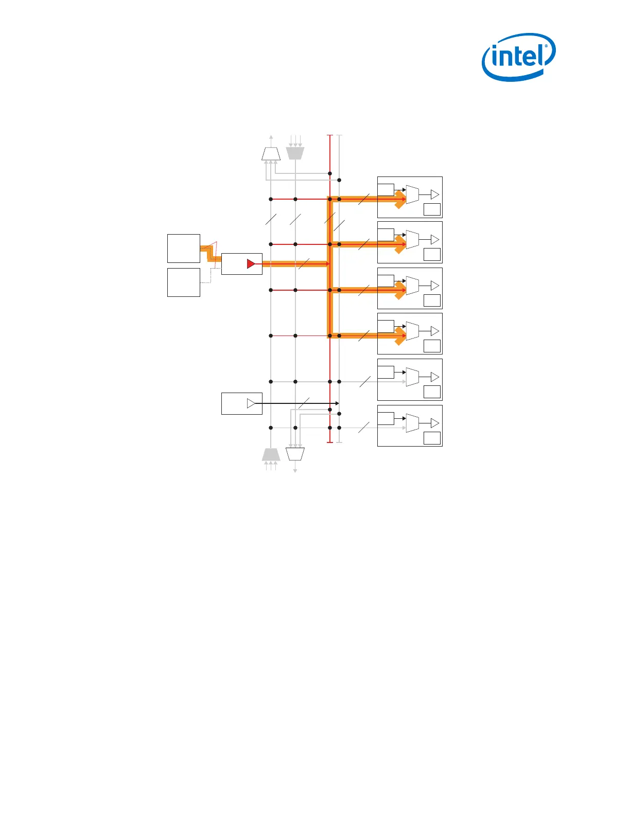
Figure 102. Use ATX PLL or fPLL for Gen1/Gen2 x4 Mode
CDR
CGB
Ch 4
CDR
CGB
Ch 3
CDR
CGB
Ch 2
CDR
CGB
Ch 1
CDR
CGB
Ch 0
CDR
CGB
Ch 5
X6
Network
6
6
6 6
6
6Master
CGB
Master
CGB
XN
Network
ATX PLL1
fPLL1
Connections Done
via X1 Network
Notes:
1. The figure shown is just one possible combination for the PCIe Gen1/Gen2 x4 mode.
2. The x6 and xN clock networks are used for channel bonding applications.
3. Each master CGB drives one set of x6 clock lines.
4. Gen1/Gen2 x4 modes use the ATX PLL or fPLL only.
6.
5. Use the pll_pcie_clk from either the ATX or fPLL. This is the hclk required by the PIPE interface.
In this case the Master PCS channel is logical channel 3 (physical channel 4).
2. Implementing Protocols in Arria 10 Transceivers