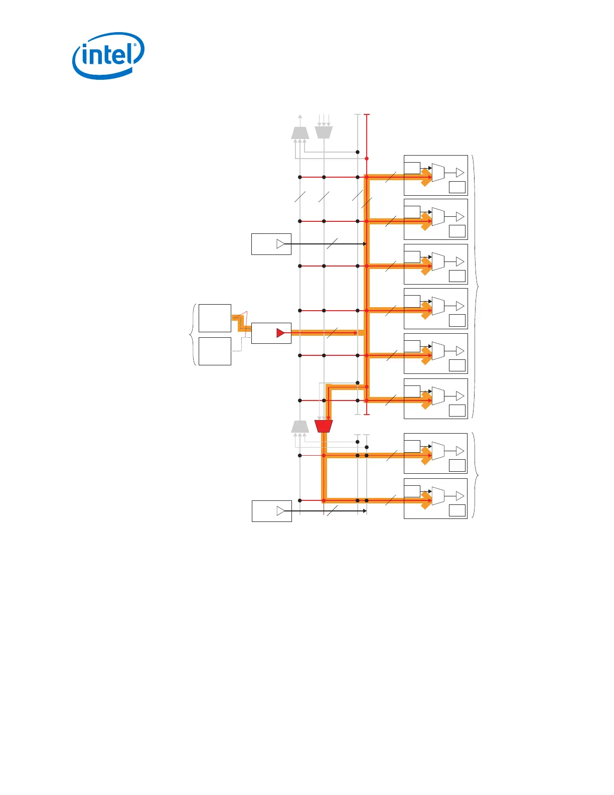
Figure 103. Use ATX PLL or fPLL for Gen1/Gen2 x8 Mode
CDR
CGB
Ch 4
CDR
CGB
Ch 3
CDR
CGB
Ch 2
CDR
CGB
Ch 1
CDR
CGB
Ch 0
CDR
CGB
Ch 5
6
6
6
6
Master
CGB
6
6Master
CGB
ATX PLL1
fPLL1
Connections Done
via X1 Network
Notes:
1. Figure shown is just one possible combination for the PCIe Gen1/Gen2 x8 mode.
2. The x6 and xN clock networks are used for channel bonding applications.
3. Each master CGB drives one set of x6 clock lines. The x6 lines further drive the xN lines.
4. Gen1/Gen2 x8 mode uses the ATX PLL or fPLL only.
6. In this case the Master PCS channel is logical channel 4 (Ch 1 in the top bank).
5. Use the pll_pcie_clk from either the ATX or fPLL. This is the hclk required by the PIPE interface.
CDR
CGB
Ch 5
CDR
CGB
Ch 4
Use Any
One PLL
Transceiver
bank
Transceiver
bank
6
Master
CGB
2. Implementing Protocols in Arria 10 Transceivers