assignments. Each TX channel has its own TX bit slip assignment and the bit slip
amount is relative to the other TX channels. You can improve lane-to-lane skew by
assigning TX bit slip ports with proper values.
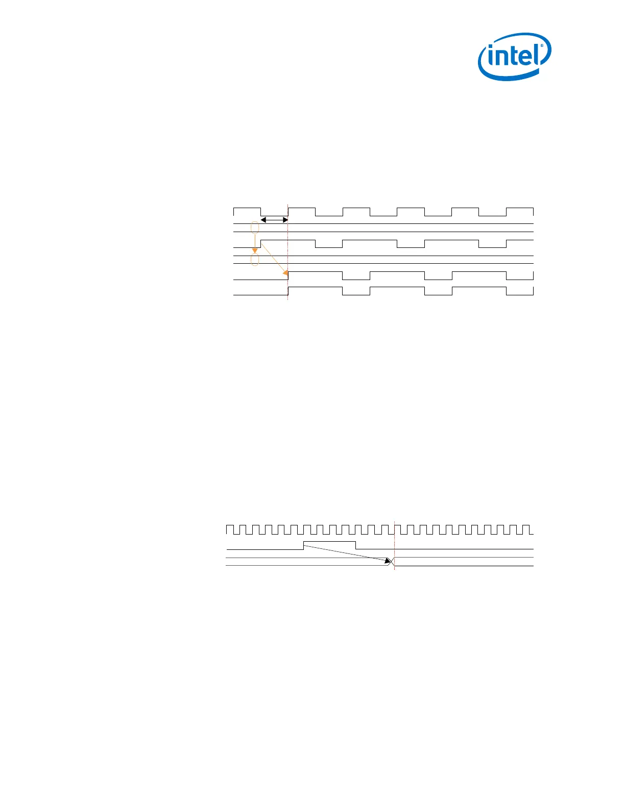
The following figure shows the effect of slipping tx_serial_data[0] by one UI to
reduce the skew with tx_serial_data[1]. After the bit slip, tx_serial_data[0]
and tx_serial_data[1] are aligned.
Figure 128. TX Bit Slip
tx_serial_clock
tx_enh_bitslip[0]
tx_serial_data[0] (Before)
tx_enh_bitslip[0]
tx_serial_data[0] (After)
tx_serial_data[1]
0000000
0000001
1 UI
2.9.1.6. TX Data Polarity Inversion
Use the TX data polarity inversion feature to swap the positive and negative signals of
a serial differential link if they were erroneously swapped during board layout. To
enable TX data polarity inversion, select the Enable TX data polarity inversion
option in the Gearbox section of Platform Designer (Standard). It can also be
dynamically controlled with dynamic reconfiguration.
2.9.1.7. RX Data Bitslip
The RX data bit slip in the RX gearbox allows you to slip the recovered data. An
asynchronous active high edge on the rx_bitslip port changes the word boundary,
shifting rx_parallel_data one bit at a time. Use the rx_bitslip port with its own
word aligning logic. Assert the rx_bitslip signal for at least two parallel clock cycles
to allow synchronization. You can verify the word alignment by monitoring
rx_parallel_data. Using the RX data bit slip feature is optional.
Figure 129. RX Bit Slip
rx_clkout
rx_bitslip
rx_parallel_data[63:0]
64’d164’d0
2.9.1.8. RX Data Polarity Inversion
Use the RX data polarity inversion feature to swap the positive and negative signals of
a serial differential link if they were erroneously swapped during board layout. To
enable RX data polarity inversion, select the Enable RX data polarity inversion
option in the Gearbox section of Platform Designer (Standard). It can also be
dynamically controlled with dynamic reconfiguration.
2. Implementing Protocols in Arria 10 Transceivers
UG-01143 | 2018.06.15
Intel
®
Arria
®
10 Transceiver PHY User Guide
299