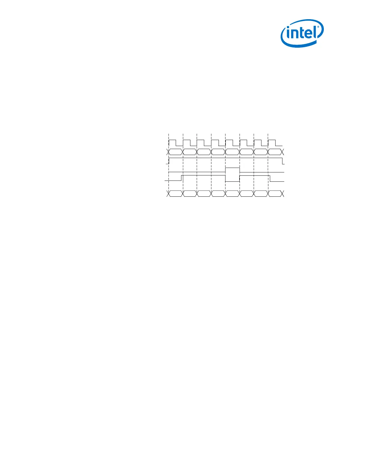
The following figure shows the current running disparity being altered in Basic single-
width mode by forcing a positive disparity /K28.5/ when it was supposed to be a
negative disparity /K28.5/. In this example, a series of /K28.5/ code groups are
continuously being sent. The stream alternates between a positive running disparity
(RD+) /K28.5/ and a negative running disparity (RD-) /K28.5/ to maintain a neutral
overall disparity. The current running disparity at time n + 3 indicates that the /K28.5/
in time n + 4 should be encoded with a negative disparity. Because tx_forcedisp is
high at time n + 4, and tx_dispval is low, the /K28.5/ at time n + 4 is encoded as a
positive disparity code group.
Figure 152. 8B/10B TX Disparity Control
Current Running Disparity
clock
tx_in[7:0]
tx_forcedisp
BC BC BC BC BC BC BC
tx_ctrlenable
BC
dataout[9:0]
17C 283
RD–
17C
RD–RD+
283
RD+
283
RD+
283
RD+
17C
RD–
17C
RD–
n n + 1 n + 2 n + 3 n + 4 n + 5 n + 6 n + 7
tx_dispval
2.9.2.11. How to Enable Low Latency in Basic
In the Arria 10 Transceiver Native PHY IP Parameter Editor, use the following settings
to enable low latency:
1. Select the Enable 'Standard PCS' low latency mode option.
2. Select either low_latency or register FIFO in the TX FIFO mode list.
3. Select either low_latency or register FIFO in the RX FIFO mode list.
4. Select either Disabled or Serialize x2 in the TX byte serializer mode list.
5. Select either Disabled or Serialize x2 in the RX byte deserializer mode list.
6. Ensure that RX rate match FIFO mode is disabled.
7. Set the RX word aligner mode to bitslip.
8. Set the RX word aligner pattern length to 7 or 16.
Note: TX bitslip, RX bitslip, bit reversal, and polarity inversion modes are
supported.
2.9.2.12. TX Bit Slip
To use the TX bit slip, select the Enable TX bitslip and Enable
tx_std_bitslipboundarysel port options. This adds the
tx_std_bitslipboundarysel input port. The TX PCS automatically slips the
number of bits specified by tx_std_bitslipboundarysel. There is no port for TX
bit slip. If there is more than one channel in the design,
tx_std_bitslipboundarysel ports are multiplied by the number of channels. You
can verify this feature by monitoring the tx_parallel_data port.
Enabling the TX bit slip feature is optional.
2. Implementing Protocols in Arria 10 Transceivers
UG-01143 | 2018.06.15
Intel
®
Arria
®
10 Transceiver PHY User Guide
311