Note:
tx_analog_reset_ack and rx_analog_reset_ack must be treated as
asynchronous signals. You must pass them through a synchronizer before sending
them to control logic.
4.3.2.1. Recommended Reset Sequence
4.3.2.1.1. Resetting the Transmitter During Device Operation
The numbers in this list correspond to the numbers in the following figure.
1.
Assert tx_analogreset, pll_powerdown, and tx_digitalreset, while
pll_cal_busy and tx_cal_busy are low.
2.
Wait for tx_analogreset_ack to go high, to ensure successful assertion of
tx_analogreset. tx_analogreset_ack goes high when TRS has successfully
completed the reset request for assertion.
a.
Deassert pll_powerdown after t
pll_powerdown
.
b.
Deassert tx_analogreset. This step can be done at the same time or after
you deassert pll_powerdown.
3.
Wait for tx_analogreset_ack to go low, to ensure successful deassertion of
tx_analogreset. tx_analogreset_ack goes low when TRS has successfully
completed the reset request for deassertion.
4.
The pll_locked signal goes high after the TX PLL acquires lock. Wait for
tx_analogreset_ack to go low before monitoring the pll_locked signal.
5.
Deassert tx_digitalreset a minimum t
tx_digitalreset
time after pll_locked
goes high.
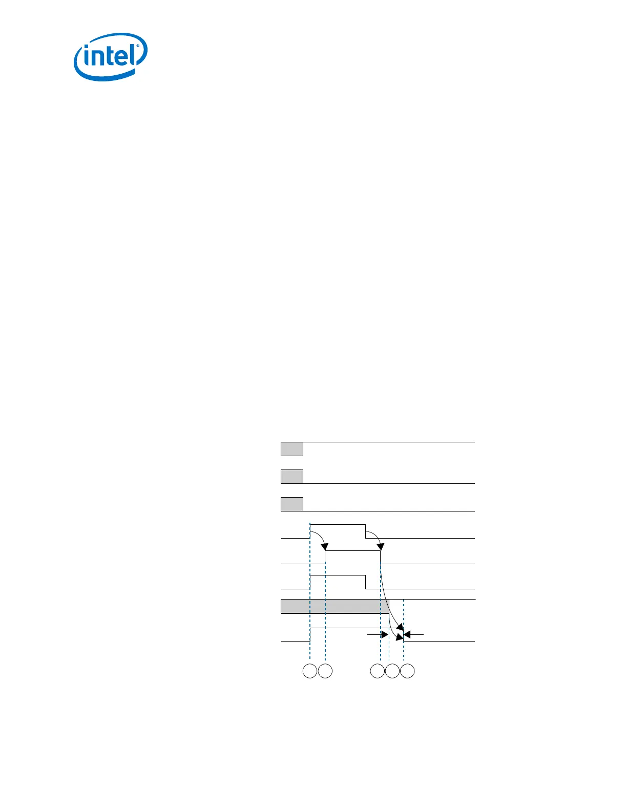
Figure 210. Transmitter Reset Sequence During Device Operation
Device Power Up
pll_cal_busy
tx_cal_busy
tx_analogreset
pll_powerdown
pll_locked
tx_analogreset_ack
1 2 3 54
tx_digitalreset
t
tx_digitalreset
(1) Area in gray is don’t care logic state.
Note:
4. Resetting Transceiver Channels
UG-01143 | 2018.06.15
Intel
®
Arria
®
10 Transceiver PHY User Guide
428