4.3.2.1.2. Resetting the Receiver During Device Operation
The numbers in this list correspond to the numbers in the following figure.
1.
Assert rx_analogreset and rx_digitalreset while rx_cal_busy is low.
2.
Wait for rx_analogreset_ack to go high, to ensure successful assertion of
rx_analogreset. rx_analogreset_ack goes high when TRS has successfully
completed the reset request for assertion.
a.
Deassert rx_analogreset.
3.
Wait for rx_analogreset_ack to go low, to ensure successful deassertion of
rx_analogreset. rx_analogreset_ack goes low when TRS has successfully
completed the reset request for deassertion.
4.
The rx_is_lockedtodata signal goes high after the CDR acquires lock.
5.
Ensure rx_is_lockedtodata is asserted for t
LTD
(minimum of 4 μs) before
deasserting rx_digitalreset.
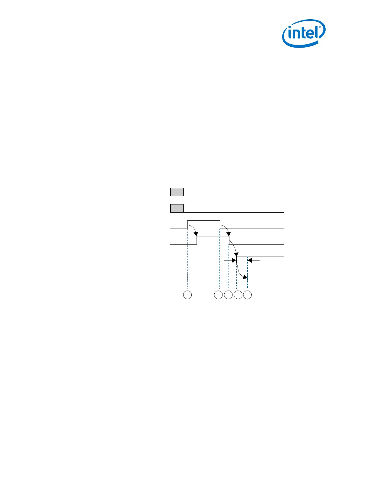
Figure 211. Receiver Reset Sequence During Device Operation
Device Power Up
rx_cal_busy
rx_analogreset
rx_is_lockedtodata
rx_digitalreset
rx_analogreset_ack
1 2 543
t
LTD
min 4 μs
4.3.2.1.3. Dynamic Reconfiguration of Transmitter Channel Using the Acknowledgment
Model
The numbers in this list correspond to the numbers in the following figure.
1.
Assert tx_analogreset, pll_powerdown, and tx_digitalreset, while
pll_cal_busy and tx_cal_busy are low.
2.
Wait for tx_analogreset_ack to go high, to ensure successful assertion of
tx_analogreset. tx_analogreset_ack goes high when TRS has successfully
completed the reset request for assertion.
4. Resetting Transceiver Channels
UG-01143 | 2018.06.15
Intel
®
Arria
®
10 Transceiver PHY User Guide
429