5.3.2.4. 8B/10B Decoder
The general functionality for the 8B/10B decoder is to take a 10-bit encoded value as
input and produce an 8-bit data value and a 1-bit control value as output. In
configurations with the rate match FIFO enabled, the 8B/10B decoder receives data
from the rate match FIFO. In configurations with the rate match FIFO disabled, the
8B/10B decoder receives data from the word aligner. The 8B/10B decoder operates in
two conditions:
• When the PCS-PMA interface width is 10 bits and FGPA fabric-PCS interface width
is 8 bits
• When the PCS-PMA interface width is 20 bits and FPGA fabric-PCS interface width
is 16 bits
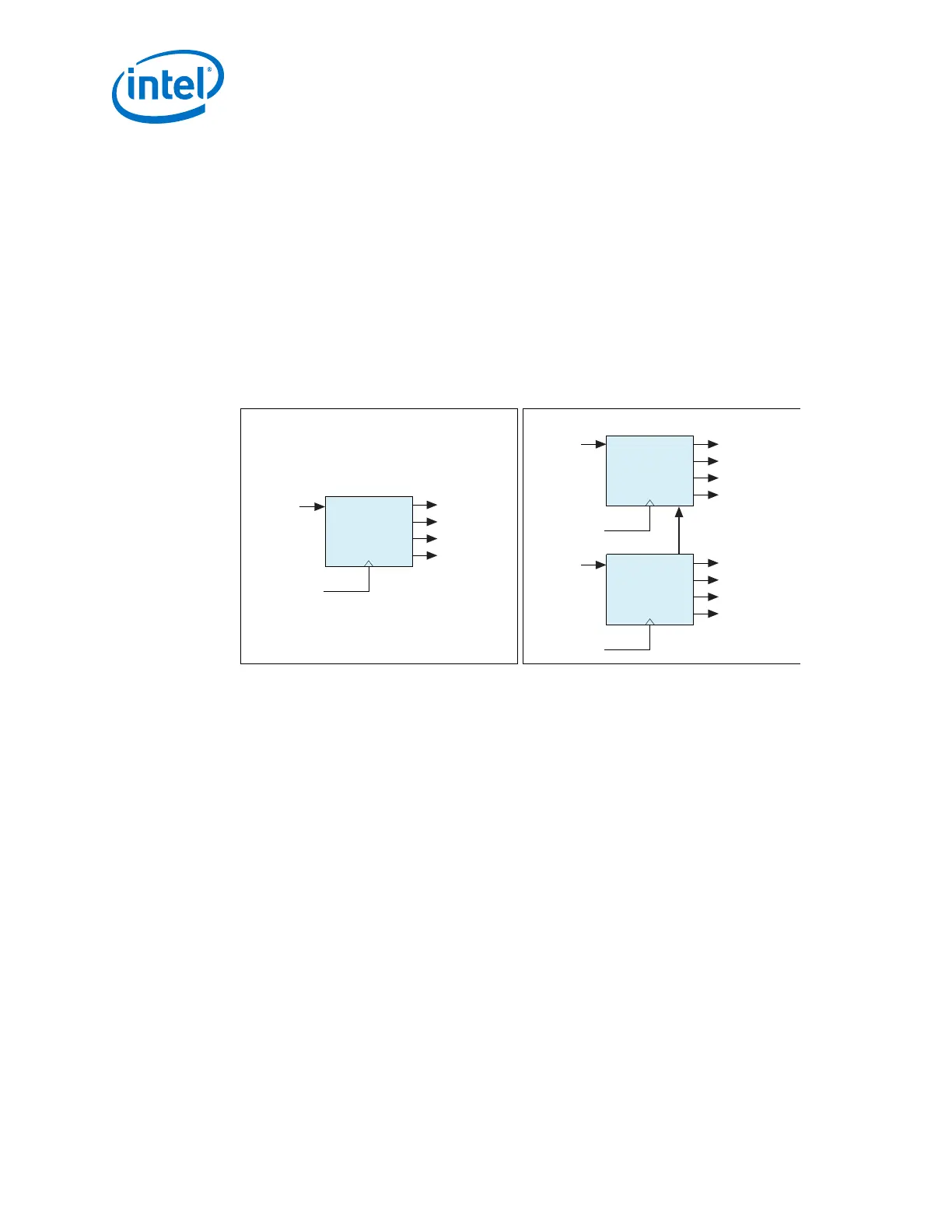
Figure 260. 8B/10B Decoder in Single-Width and Double-Width Mode
Single-Width Mode
Current Running Disparity
datain[19:10]
rx_dataout[15:8]
rx_datak[1]
rx_errdetect[1]
rx_disperr[1]
recovered clock or
tx_clkout[0]
datain[9:0]
rx_dataout[7:0]
rx_datak[0]
rx_errdetect[0]
rx_disperr[0]
recovered clock or
tx_clkout[0]
Double-Width Mode
8B/10B Decoder
(MSByte)
8B/10B Decoder
(LSByte)
datain[9:0]
rx_dataout[7:0]
rx_datak
rx_errdetect
rx_disperr
recovered clock or
tx_clkout[0]
8B/10B Decoder
(LSByte)
When the PCS-PMA interface width is 10 bits, only one 8B/10B decoder is used to
perform the conversion. When the PCS-PMA interface width is 20 bits, two cascaded
8B/10B decoders are used. The 10-bit LSByte of the received 20-bit encoded data is
decoded first and the ending running disparity is forwarded to the 8B/10B decoder
responsible for decoding the 10-bit MSByte. The cascaded 8B/10B decoder decodes
the 20- bit encoded data into 16-bit data + 2-bit control identifier. The MSB and LSB
of the 2-bit control identifier correspond to the MSByte and LSByte of the 16-bit
decoded data code group. The decoded data is fed to the byte deserializer or the RX
FIFO.
5. Arria 10 Transceiver PHY Architecture
UG-01143 | 2018.06.15
Intel
®
Arria
®
10 Transceiver PHY User Guide
492