Chapter 5 Parameters Definition
94
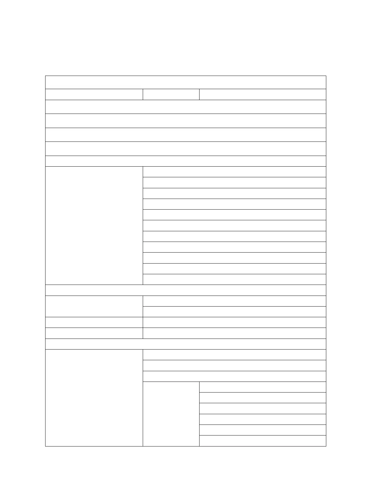
The Service Menu Structure table displays the full Service Menu structure. Use the
Table of Contents at the beginning of this manual as appropriate to locate the
explanation of each menu item.
Table 8 Service Menu Structure
F1 – Place in Normal Service (Access Level 1)
F1 – Place in Conditional Service (Access Level 1)
F1 – Place in No Database Conditional Service (Access Level 1)
Shift+F1 – Place in Krypton Mode Service (Access Level 1)
F2 – Test Menu (Access Level 2)
F1 – Rate Meter
F2 – HVPS Meter
F3 – Counter Test
F4 – Amplifier Pulse Test
F7 – Timer Tests
F8 – Discriminator Plot (Access Level 2)
F9 – Plateau Plot (Access Level 2)
F10 – Detector Board ID
F11 – Carrier Board Tests
F12 – Background Trend Graph (Access Level 2)
Shift+F2 – Additional Test Menu (Access Level 2)
F1 – Optimize Gamma HV (Access Level 2)
F2 – Optimize Self Shield Factors
F3 – Test Auxiliary Sensor Boards
F7 – Barrier Exercise
F3 – Setup Menu (Access Level 2)
F1 – Common Values
F3 – Detection Zones (Access Level 2)
F1 – Zone Configuration
F2 – (Zone) Settings
F3 – Calibration (Access Level 2)
Shift+F3 – Calibration Settings
F5 – Group Settings (Access Level 2)
Shift+F5 – Global Settings