Sensor Boards
Gem-5 User’s Manual 347
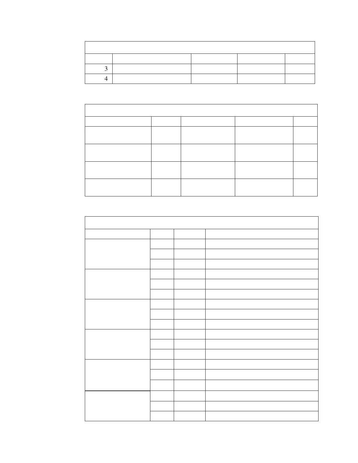
Table 38 Sensor Polarity Switch Settings
SW6-3 NOT USED N/A N/A N/A
SW6-4 NOT USED N/A N/A N/A
Table 39 Relay Output Switch Settings
Switch Relay OFF ON LED
SW1-1
Relay 1
(TB3)
NORMALLY
ENERGIZED
NORMALLY
DE-ENERGIZED
D18
SW1-2
Relay 2
(TB4)
NORMALLY
ENERGIZED
NORMALLY
DE-ENERGIZED
D9
SW1-3 (Cronos: Front
Door Lock)
Relay 3
(TB5)
NORMALLY
ENERGIZED
NORMALLY
DE-ENERGIZED
D19
SW1-4 (Cronos: Rear
Door Lock)
Relay 4
(TB6)
NORMALLY
ENERGIZED
NORMALLY
DE-ENERGIZED
Table 40 Sensors/Switches Terminal Blocks Pin Assignments
(TB18)
3 IN APPROACH SENSOR 1 INPUT
APPROACH 2 (TB9) 1 GND GROUND
2 +12 V +12 V POWER
3 IN APPROACH SENSOR 2 INPUT
OCCUPIED (TB19) 1 GND GROUND
3 IN OCCUPIED SENSOR INPUT
HAND 1 (TB10) 1 GND GROUND
2 +12 V +12 V POWER
3 IN HAND SENSOR 1 INPUT
HAND 2 (TB20) 1 GND GROUND
2 +12 V +12 V POWER
FOOT 1 (TB11)
(Cronos: Front Door
Sensor “Closed”)
1 GND GROUND
2 +12 V +12 V POWER
3 IN FOOT SENSOR 1 INPUT