EasyManuals Logo

Mirion Technologies GEM-5 User Manual

Default Icon
443 pages
To Next Page IconTo Next Page
To Previous Page IconTo Previous Page
Page #370 background imageLoading...
Page #370 background image
Appendix I Component Details – Options
354
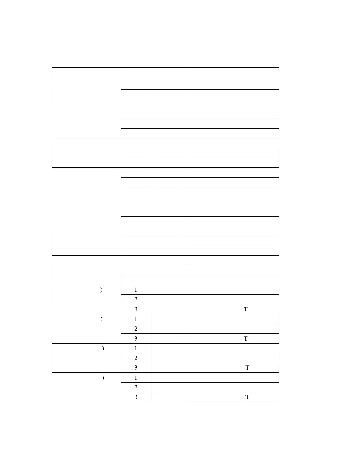
Table 45 Sensors/Switches Terminal Blocks Pin Assignments
LABEL PIN # SIGNAL DESCRIPTION
IN 1 (TB15) 1 GND GROUND
2 +12 V +12 V POWER
3 IN IN 1 INPUT
IN 2 (TB7) 1 GND GROUND
2 +12 V +12 V POWER
3
IN
IN 2 INPUT
IN 3 (TB16) 1 GND GROUND
2 +12 V +12 V POWER
3 IN IN 3 INPUT
IN 4 (TB8) 1 GND GROUND
2 +12 V +12 V POWER
3 IN IN 4 INPUT
IN 5 (TB17)
1
GND
GROUND
2 +12 V +12 V POWER
3 IN IN 5 INPUT
IN 6 (TB9) 1 GND GROUND
2 +12 V +12 V POWER
3 IN IN 6 INPUT
IN 7 (TB18) 1 GND GROUND
2
+12 V
+12 V POWER
3 IN IN 7 INPUT
IN 8 (TB10) 1 GND GROUND
2 +12 V +12 V POWER
3 IN IN 8 INPUT
IN 9 (TB19) 1 GND GROUND
2
+12 V
+12 V POWER
3
IN
IN 9 INPUT
IN 10 (TB11) 1 GND GROUND
2 +12 V +12 V POWER
3 IN IN 10 INPUT
IN 11 (TB20) 1 GND GROUND
2 +12 V +12 V POWER
3
IN
IN 11 INPUT

Table of Contents

Questions and Answers:

Question and Answer IconNeed help?

Do you have a question about the Mirion Technologies GEM-5 and is the answer not in the manual?

Mirion Technologies GEM-5 Specifications

General IconGeneral
BrandMirion Technologies
ModelGEM-5
CategoryMonitor
LanguageEnglish

Related product manuals