DMTA-10040-01EN, Rev. E, February 2018
Chapter 5128
OR
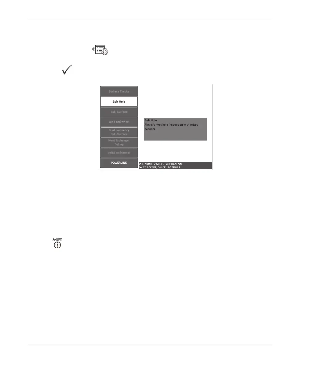
If you are using an earlier version of the software, press the ADV SETUP
menu key ( ) once, and then select APPL SELECT (A key) to open the
application selection menu. Select Bolt Hole with the knob, and then press
to accept (see Figure 5-11 on page 128).
Figure 5‑11 The Bolt Hole application
To calibrate the signals
1. Insert the probe into the “bad” hole on the standard (there are two 12.70 mm
[0.50 in.] holes: one without defects and one with a long axial notch), making sure
to properly align the probe with the hole, and then press the A-LIFT NULL key
().
Note that the scanner should be stopped when nulling the instrument.
2. Hold the probe in the hole and properly aligned on the long crack. If this is your
first scan, start the rotating scanner motor by pressing the switch at the back of the
rotating scanner.
The signal on the impedance plane (right side) should display the defect signal
and the lift-off signal (also referred to as the probe-motion signal). Depending on
the probe diameter used, the lift-off signal may appear smaller or bigger, and
sometimes the signal may be difficult to see on the screen.
If the probe is correctly aligned in the hole, the lift-off amplitude is normally
decreased, but if the probe is slightly misaligned, it will result in an increase in