DMTA-10040-01EN, Rev. E, February 2018
Using the Instrument 285
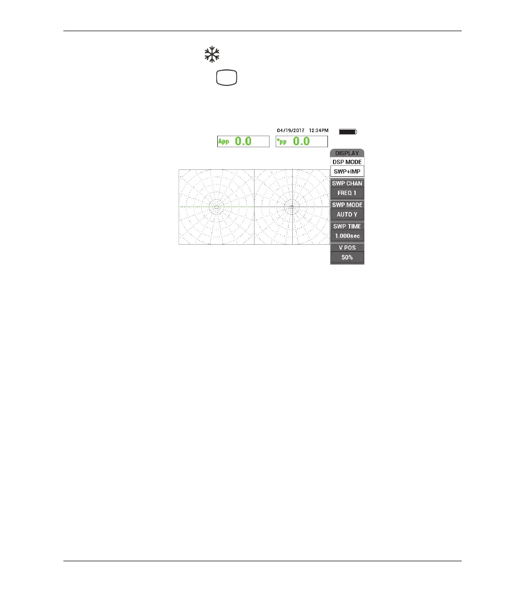
5. Press the FREEZE key ( ) to enable signal acquisition.
6. Press the DISP menu key ( ), followed by DSP MODE (display mode, A key),
and then rotate the knob until SWP + IMP (sweep plus impedance) is displayed
(see Figure 5-230 on page 285).
Figure 5‑230 The SWP + IMP display
7. Press SWP TIME (D key) and adjust the sweep time to accommodate the length
of the tube being inspected.
8. Place the probe in a defect-free area of the calibration standard near the thru-wall
hole, and then press the NULL foot switch.
9. Slowly scan the tube.
The scan result should be similar to that shown in Figure 5-231 on page 286. The
SWP (sweep) display on the left of the screen clearly shows the larger indications
(full screen) that represent the 40 % and 60 % wall-loss flaws. The center (smaller)
indication represents the thru-wall hole.