DMTA-10040-01EN, Rev. E, February 2018
Using the Instrument 289
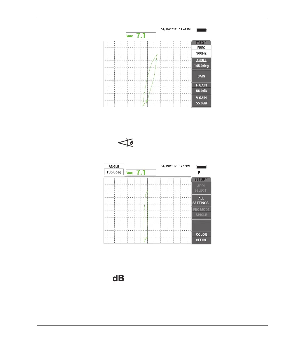
Figure 5‑235 The scan signal of the 60 % wall‑loss groove
3. Press the ANGLE key ( ), and then rotate the signal until the 60 % wall-loss
groove signal is vertical (see Figure 5-236 on page 289).
Figure 5‑236 Adjusting the signal phase
4. Press the GAIN key ( ), and then increase the gain until the flaw signal
reaches about 6 vertical divisions in height (see Figure 5-237 on page 290).
If necessary, adjust the ANGLE after you have increased the gain.