DMTA-10040-01EN, Rev. E, February 2018
Using the Instrument 135
The default filter type is a Figure 6 (FIG 6) signal, which has a needle-like shape and is
widely employed in the industry. This Figure 6 filter automatically adjusts the signal
phase in order to achieve the typical Figure 6 response, regardless of high and low
pass filter settings. This constant Figure 6 filter response enables much quicker and
easier tuning of the NORTEC 600 filter system, and it makes it possible to eliminate
unwanted signals rather than trying to achieve the proper signal shape.
The Figure 8 (FIG 8) filter type is generated using filters that are almost completely
nondistorting. This filter type is useful when using absolute rotating probes or in
special engine-inspection applications. The Figure 8 filter is also the default filter type
for nonrotating applications such as surface inspection.
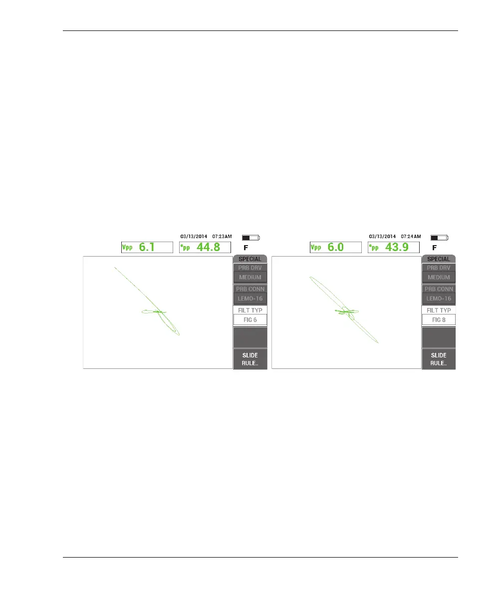
Figure 5-21 on page 135 shows the Figure 6 response on the left and the Figure 8
response on the right. Both images have been obtained using the same probe in an
aluminum hole with very similar gain and angle settings.
Figure 5‑21 Comparing the Figure 6 (left) and Figure 8 filter signals
By setting LINK to ON, you can enable the dynamic high and low pass filter settings
while you adjust RPM to maintain the signal response.
5.1.3 Detecting Sub-Surface Cracks at Very Low Frequency — All
NORTEC 600 Models
This section contains a general procedure for detecting sub-surface cracks at fastener
locations in aircraft lap joints. This procedure can easily be adapted to thicker skins
(or materials) by employing a bigger ring probe and lower frequency.