DMTA-10040-01EN, Rev. E, February 2018
Chapter 5270
3. Press V POS 2 (vertical position 2, E key), and then rotate the knob until 20 % is
displayed.
4. Place the probe in a defect-free area near the thru-wall flaw, and then press the
NULL foot switch.
5. Scan the tube for defects.
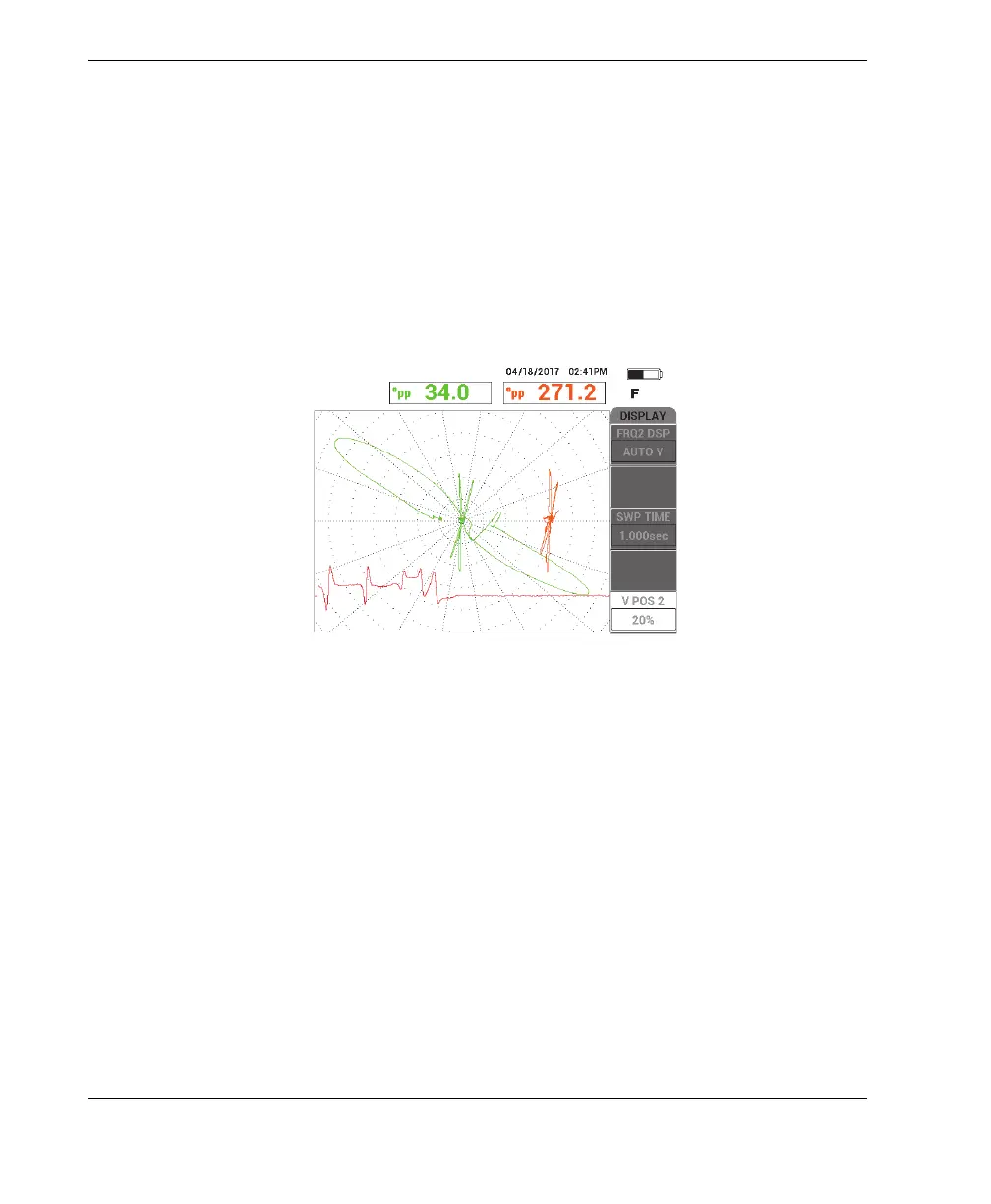
The resulting scan displays the following signals (see Figure 5-207 on page 270):
a) Frequency 1 signal (center screen)
b) MIX signal (center-right screen)
c) Frequency 2 as a strip chart (bottom screen)
Figure 5‑207 ALL‑IN‑1 display of cluster of 4 corrosion pits under support ring
6. Loosen the thumb screw on the support ring, and then slide the support ring to
within 3.2 mm (0.125 in.) of the 75 % corrosion pit.
7. Place the probe in a defect-free area near the thru-wall flaw, and then press the
NULL foot switch.
8. Scan the tube for defects.
The scan result is shown in Figure 5-208 on page 271.