DMTA-10040-01EN, Rev. E, February 2018
Using the Instrument 219
Figure 5‑138 Adjusting the frequency 1 signal phase
4. Press the GAIN key ( ), and then increase the frequency 1 gain until the hole
signal reaches about 4 vertical divisions in height (see Figure 5-139 on page 219).
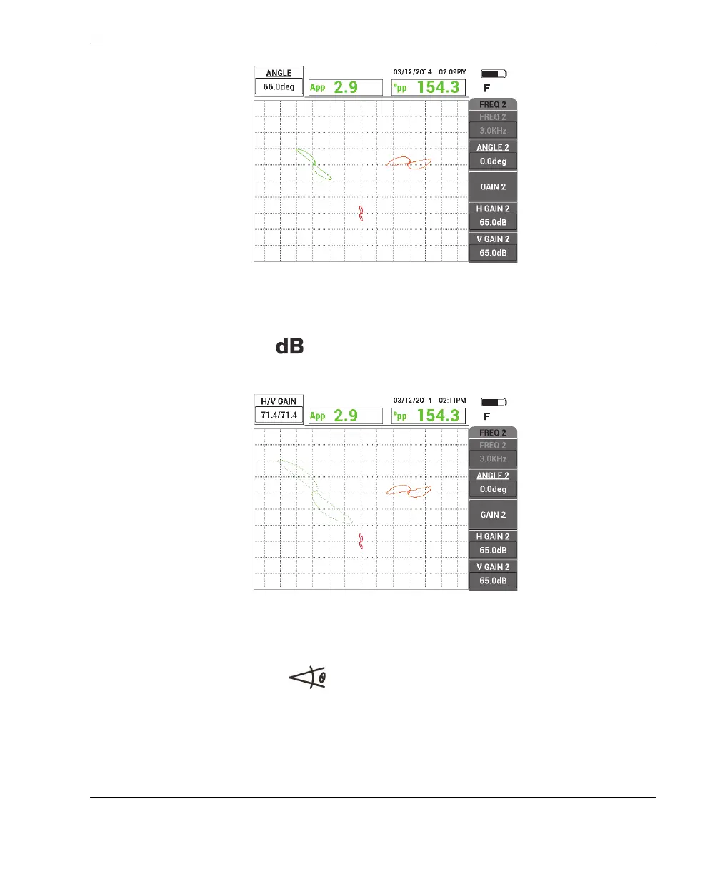
Figure 5‑139 Adjusting the frequency 1 gain
5. Press the ANGLE key ( ) twice, and then adjust the angle of the frequency 2
signal (red) until the hole signal is oriented almost vertically (see Figure 5-140 on
page 220).
Make sure that the lower signal lobe appears first on the screen while scanning
with a pulling motion.