DMTA-10040-01EN, Rev. E, February 2018
Chapter 5238
Figure 5‑164 An example of a saturated support ring signal
9. Press the FREEZE key ( ) to enable signal acquisition, and then press the NULL
foot switch.
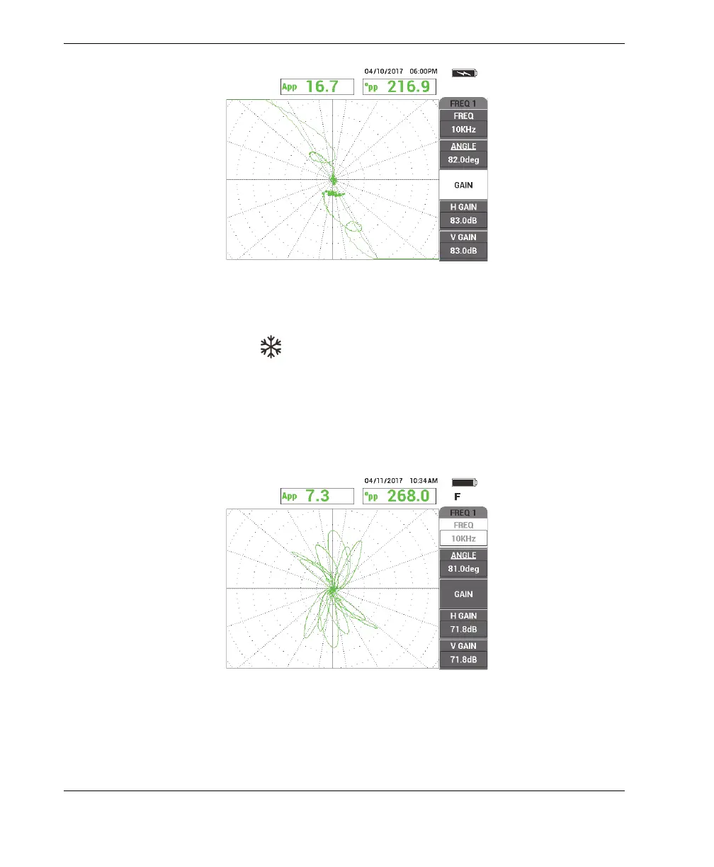
10. Scan the tube between the support ring and the 1.3 mm (0.052 in.) thru-wall hole
to verify the frequency 1 calibration (see Figure 5-165 on page 238).
For improved clarity, the verified signals of the thru-wall hole and the support
ring are shown next to each other in Figure 5-166 on page 239.
Figure 5‑165 The tube scan between the support ring and the thru‑wall hole