DMTA-10040-01EN, Rev. E, February 2018
Using the Instrument 239
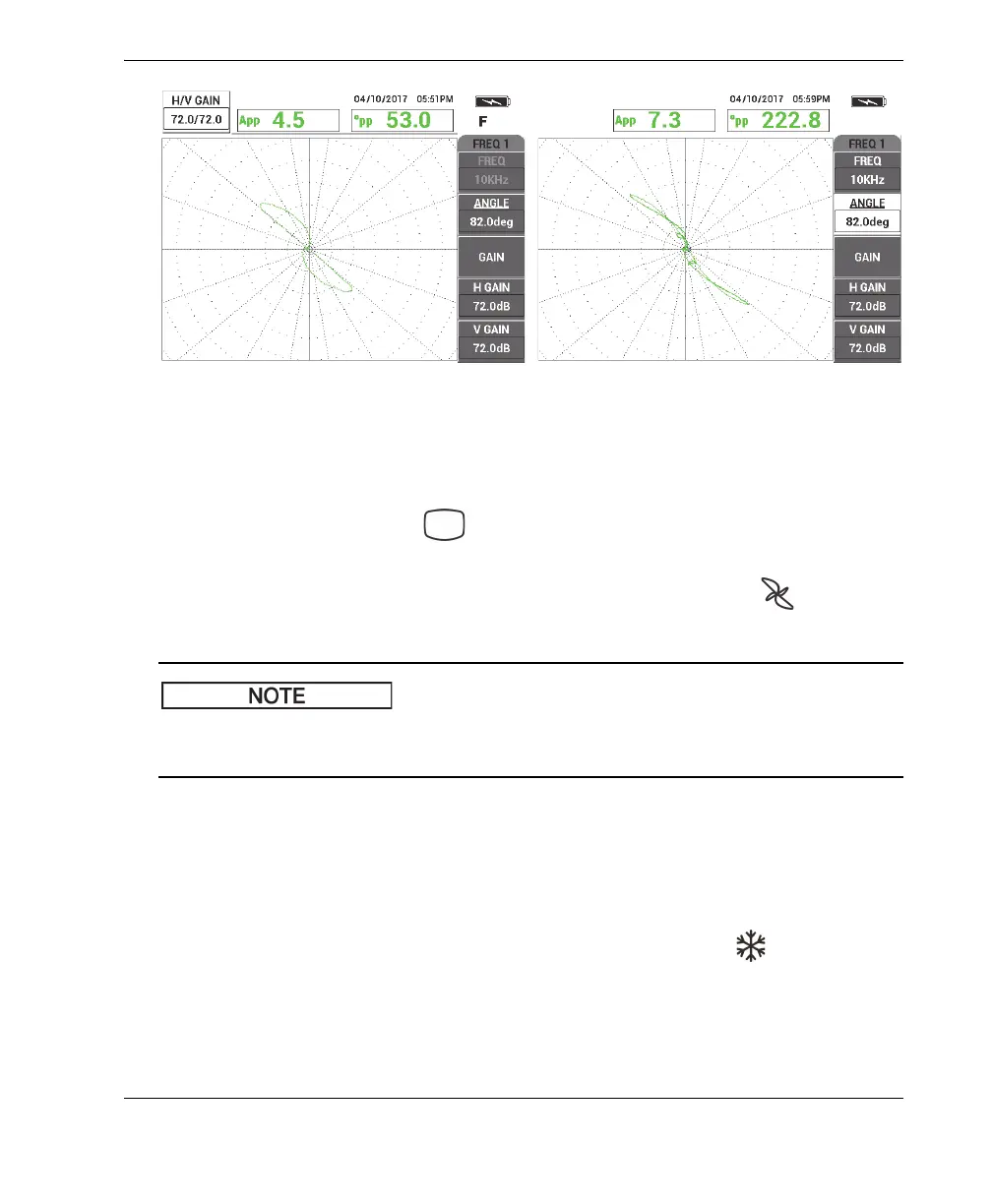
Figure 5‑166 The verified signals: thru‑wall hole (left) and support ring (right)
To calibrate the signals for frequency 2
1. Press the DISP menu key ( ), followed by CHANNEL (B key), and then rotate
the knob until FRQ2 is displayed.
2. Access the MIX menu by pressing the MAIN FILTER menu key ( ) twice to
check the frequency 2 value.
When you use the MIX function, the frequency 2 value must be at least one-half of the
frequency 1 value.
3. Place the probe in a defect-free area near the tube’s support ring, and then press
the NULL foot switch.
4. Scan the support ring and, if necessary, adjust the combined gain (H/V GAIN 2)
of frequency 2 to make sure that the signal does not exceed 80 % of full-screen
height.
5. When you obtain a satisfactory signal, press the FREEZE key ( ) to enable
signal acquisition (see Figure 5-167 on page 240).