DMTA-10040-01EN, Rev. E, February 2018
Chapter 5168
2. Ensure that the scanner motor is turned off before initial instrument nulling, place
the probe in the good hole, and then press the A-LIFT NULL key ( ).
3. Place the probe in the hole with EDM notches, and then adjust the index axis so
that the probe rotates freely next to a defect area.
Leave the scanner in the R position (rotation).
4. Turn on the scanner motor, and then press the MAIN FILTER menu key ( )
twice, and set the SCAN RPM (E key) to 240.
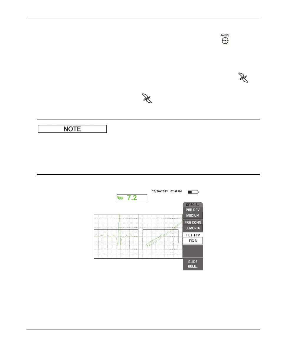
5. Press the MAIN FILTER menu key ( ), and then change the FILT TYP (C key)
to FIG 6 (see Figure 5-64 on page 168).
This procedure uses the Figure 6 filter setting. Olympus recommends using the
Figure 6 filter setting unless an absolute probe is being used, in which case the
Figure 8 filter setting might provide better performance. For more information about
the Figure 6 versus Figure 8 parameters, see “Inspecting Fastener Holes with a
Rotating Scanner — NORTEC 600S and NORTEC 600D Models” on page 126.
Figure 5‑64 The Figure 6 filter