DMTA-10040-01EN, Rev. E, February 2018
Using the Instrument 235
Figure 5‑159 Example of lower signal lobe when pulling the probe over a flaw
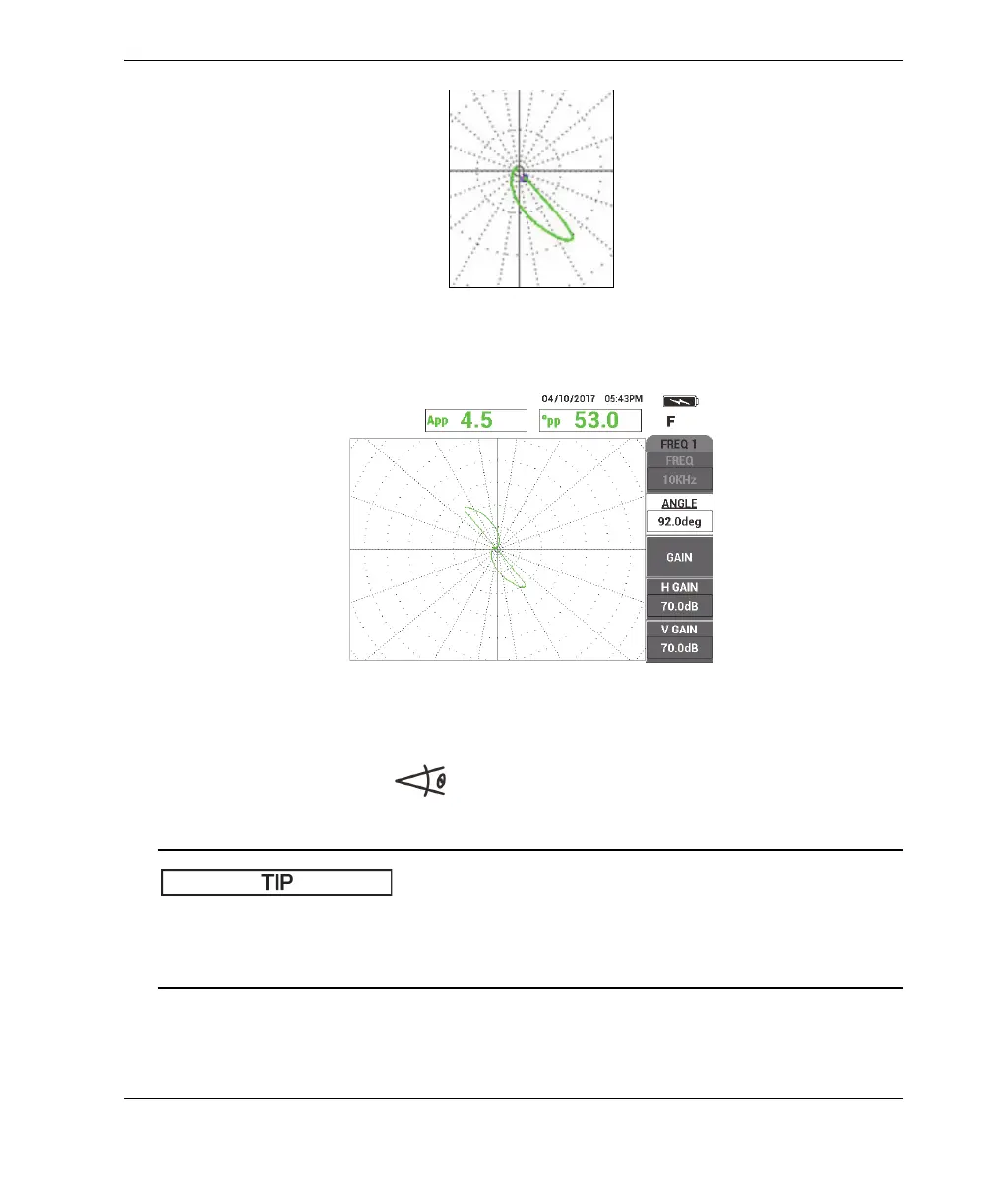
Figure 5‑160 The scan signal of the thru‑wall hole
3. Press the ANGLE key ( ), and then rotate the frequency 1 signal (green) until
the hole signal reaches a phase of about 40° (see Figure 5-161 on page 236).
Choose the polar (WEB) grid shown in this example to make it easier to adjust the
phase angle and gain. (For details on grid selection, see “GRID” on page 90.) Each
major graticule represents 20° and 10 % of full-screen height.