DMTA-10040-01EN, Rev. E, February 2018
Using the Instrument 273
To set the initial NORTEC 600 configuration
1. Connect the adaptor, probe, and foot-switch adaptor cable to the PROBE
connector on the NORTEC 600.
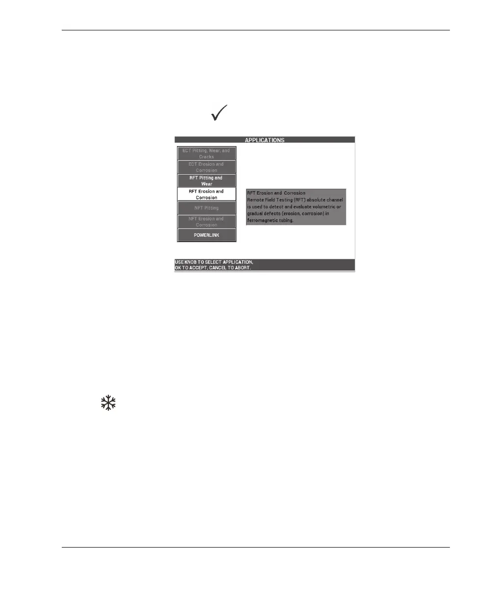
2. Select CONTINUE (press the A key), and then use the knob to select RFT Erosion
and Corrosion, and press to accept (see Figure 5-212 on page 273).
Figure 5‑212 The RFT Erosion and Corrosion application
To calibrate the signals
1. Place the probe in a defect-free area of the calibration standard near the 10 % ID
flaw, and then press the NULL foot switch.
2. Slowly scan the tube until the 40 % ID and 60 % OD flaws are displayed. When
the groove signals are visible on the NORTEC 600 screen, press the FREEZE key
( ) [see Figure 5-213 on page 274].