DMTA-10040-01EN, Rev. E, February 2018
Chapter 5132
Note that the NORTEC 600 features a constant “figure-6” rotating bolt-hole signal
response. In theory, filter adjustment is unnecessary, and only the scanner speed
(SCAN RPM) needs to be adjusted.
7. If the flaw appears at an inconvenient location in the sweep (strip chart) view on
the left, press the DISP menu key ( ) and adjust the SYNC ANG (D key) with
the knob until it is in a satisfactory location.
To fine-tune the instrument settings for aluminum
1. Depending on your requirements, set the alarm parameters, horn, or external
horn (louder). For more details about alarms, see “Alarm Menus” on page 292.
2. Check if any other display modes, such as the IMP and the WATERFALL display
modes, might be useful for your purposes. For more details about screen options,
see “Display Menu — DISP Key” on page 87 and “Display Menu in Dual
Frequency — DISP Key” on page 116.
3. Press the FULL NEXT key ( ) to toggle to the full-screen mode, and then insert
the probe into the bad hole.
The results should resemble the image in Figure 5-17 on page 132. The list of all
parameters for aluminum is shown in Figure 5-18 on page 133.
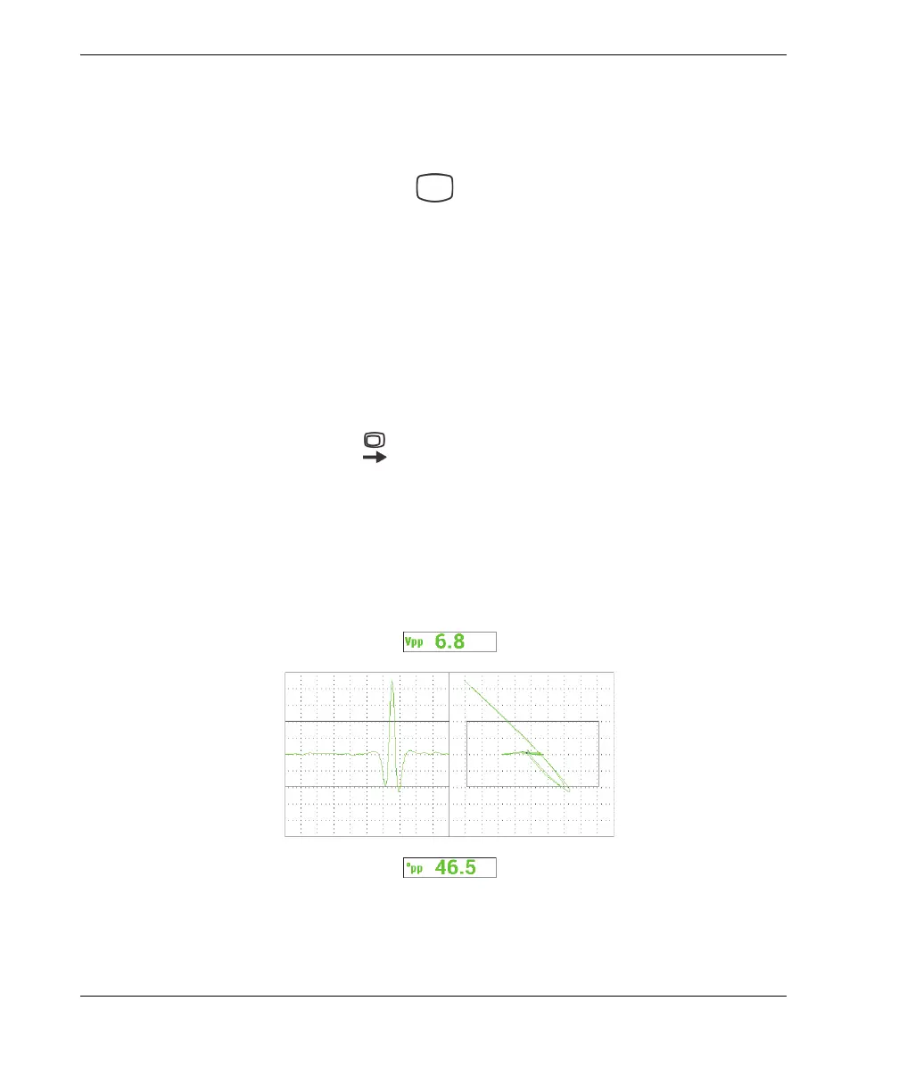
Note that the value of the maximum signal amplitude and signal angle is
displayed by default. For more details about the readings or their position in the
impedance plane display, see “Displaying Real-Time Readings” on page 56.
Figure 5‑17 The full‑screen mode for fine‑tuning the settings