DMTA-10040-01EN, Rev. E, February 2018
Using the Instrument 145
probe’s longest face still parallel to the notches), and then press the A-LIFT NULL
key ( ) to scan the entire standard.
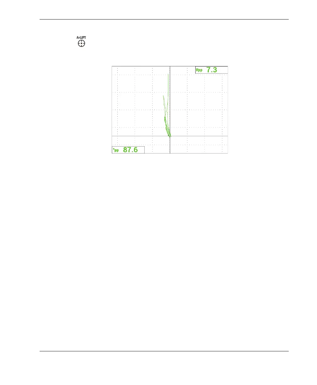
The resulting signal is shown in Figure 5-36 on page 145.
Figure 5‑36 The signal after scanning the entire standard
To fine-tune the instrument settings
1. Depending on your requirements, set the alarm parameters, horn, or external
horn (louder). For more details about alarms, see “Alarm Menus” on page 292.
2. Depending on your requirements, set the display erase or persistence values to
automatically refresh the screen. For more details about screen erase options, see
“D ERASE (display erase)” on page 89 and “PERSIST (variable persistence)” on
page 89.
You can also check if any other grids and screen display modes might be useful
for your purposes; for example, SWP+IMP. For more details about screen options,
see “Display Menu — DISP Key” on page 87 and “Display Menu in Dual
Frequency — DISP Key” on page 116.
3. Confirm that the value of the maximum signal amplitude and signal angle are
displayed by default, as shown in the example in Figure 5-37 on page 146. For
more details about the reading type or position in the impedance plane display,
see “Displaying Real-Time Readings” on page 56.