DMTA-10040-01EN, Rev. E, February 2018
Using the Instrument 291
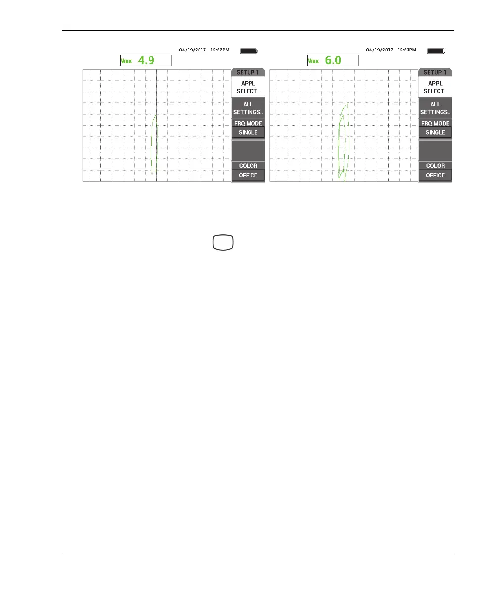
Figure 5‑238 The 40 % wall‑loss groove (left) and 60 % wall‑loss groove (right)
6. Press the DISP menu key ( ), followed by DSP MODE (display mode, A key),
and then rotate the knob until SWP + IMP (sweep plus impedance) is displayed.
7. Press SWP TIME (D key) and adjust the sweep time to accommodate the length
of the tube being inspected.
8. Place the probe in a defect-free area of the calibration standard near the 60 % wall-
loss flaw, and then press the NULL foot switch.
9. Slowly scan the tube.
The scan result should be similar to that shown in Figure 5-239 on page 292. The
SWP (sweep) display on the left of the screen clearly shows the flaws in the tube.
The larger indications (full screen) represent the 40 % and 60 % wall-loss flaws.
The center (very small) indication represents the thru-wall hole.