DMTA-10040-01EN, Rev. E, February 2018
Specifications 339
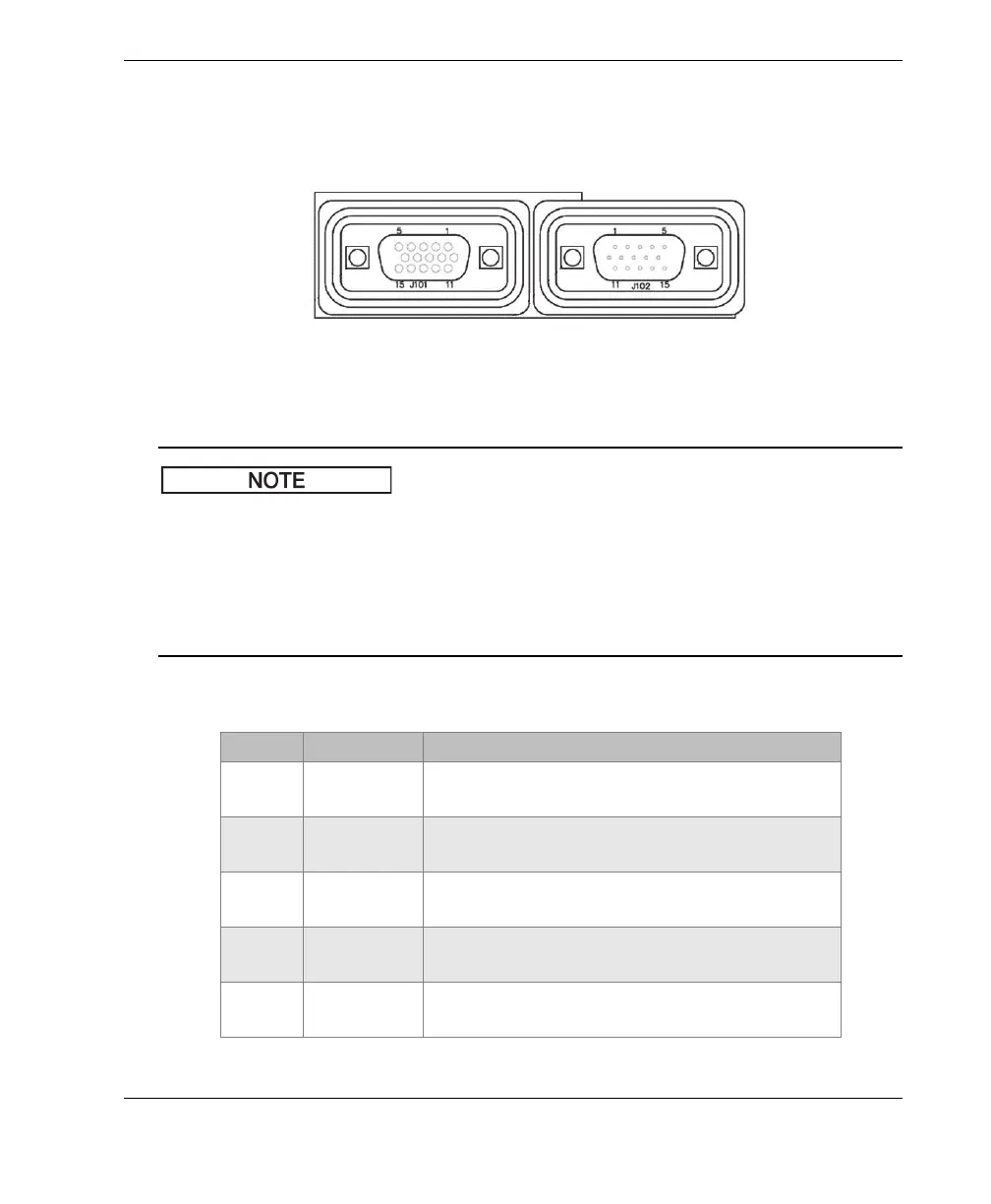
Table 9 on page 339 describes all the connections available on the 15-pin I/O
connector. Table 10 on page 340 describes all the connections available on the VGA
OUT 15-pin connector. Connector-pin numbering is shown in Figure A-1 on page 339.
Figure A‑1 Pin numbers on connectors
The NORTEC 600 instrument incorporates an alarm output (high = 5 V [on] and
low = 0 V [off]). The alarm output is not intended to directly operate devices at a
current and voltage different from that used by the NORTEC 600’s dedicated external
alarm. However, the alarm output can be used to control logic-type actuated relays,
which in turn can control other electromechanical devices such as magnetic coil
relays, indication lights, etc.
Table 9 NORTEC 600 Input/Output 15‑pin I/O connector
Pin Signal Description
1 AOUT_1 Analog Output 1 (−5V to +5V)
Meaning: F1 X
2 AOUT_2 Analog Output 2 (−5V to +5V)
Meaning: F1 Y
3 AOUT_3 Analog Output 3 (−5V to +5V)
Meaning: F2 X
4 AOUT_4 Analog Output 4 (−5V to +5V)
Meaning: F2 Y
5 AOUT_5 Analog Output 5 (−5V to +5V)
Meaning: Mix X
 Loading...


