DMTA-10040-01EN, Rev. E, February 2018
Using the Instrument 131
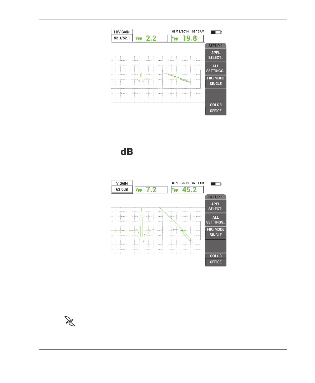
Figure 5‑15 Adjusting the gain
5. Press the GAIN key ( ) two more times to access the V GAIN parameter, and
then adjust the vertical gain with the knob until the signal reaches the top of the
screen, which is 100 % screen height (see Figure 5-16 on page 131).
Figure 5‑16 Adjusting the vertical gain
At this point, the configuration is nearly finished.
6. If required, fine-tune the filter values by pressing the MAIN FILTER menu key
( ) twice to access the HI PASS (A key), LO PASS (B key) or SCAN RPM
(E key) parameters and adjusting these parameters while maintaining the probe
rotating in the bad hole.