RL78/F13, F14 CHAPTER 16 SERIAL INTERFACE IICA
R01UH0368EJ0210 Rev.2.10 1090
Dec 10, 2015
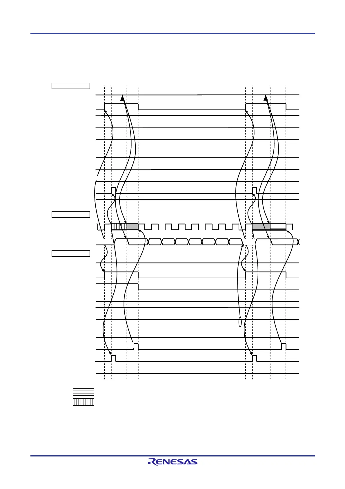
Figure 16-32. Example of Master to Slave Communication
(When 9-Clock Wait Is Selected for Master, 9-Clock Wait Is Selected for Slave) (2/4)
(2) Address ~ data ~ data
IICA0
STT0
(ST trigger)
SPT0
(SP trigger)
ACKD0
(ACK detection)
WTIM0
(8 or 9 clock wait)
ACKE0
(ACK control)
MSTS0
(communication status)
TRC0
(transmit/receive)
SCLA0 (bus)
(clock line)
WREL0
(wait cancellation)
INTIICA0
(interrupt)
SDAA0 (bus)
(data line)
IICA0
STD0
(ST detection)
SPD0
(SP detection)
ACKD0
(ACK detection)
WTIM0
(8 or 9 clock wait)
ACKE0
(ACK control)
MSTS0
(communication status)
TRC0
(transmit/receive)
WREL0
(wait cancellation)
INTIICA0
(interrupt)
W ACK
Master side
Bus line
Slave side
H
H
L
H
L
L
L
H
H
L
L
D
16 D15 D14 D13 D12 D11 D10
D17
D27
ACK
H
Note 2
<10>
<6>
<7>
<8>
<3>
<4>
Note 1 Note 1
<9>
<5>
Note 2
: Wait state by slave device
: Wait state by master and slave devices
Notes 1. Write data to IICA0, not setting the WREL0 bit, in order to cancel a wait state during transmission by a
master device.
2. For releasing wait state during reception of a slave device, write “FFH” to IICA0 or set the WREL0 bit.

 Loading...


