RL78/F13, F14 CHAPTER 9 REAL-TIME CLOCK
R01UH0368EJ0210 Rev.2.10 665
Dec 10, 2015
9.3.7 Real-time clock control register 1 (RTCC1)
The RTCC1 register is an 8-bit register that is used to control the alarm interrupt function and the wait time of the
counter.
Set the RTCC1 register by a 1-bit or 8-bit memory manipulation instruction.
Reset signal generation clears this register to 00H.
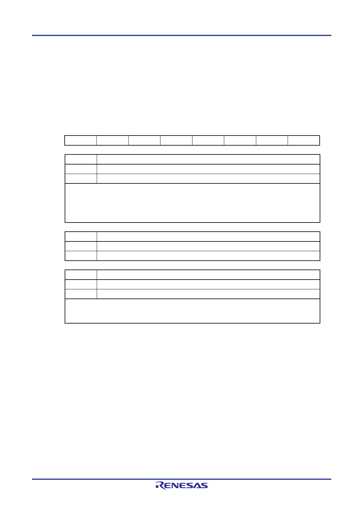
Figure 9-8. Format of Real-time Clock Control Register 1 (RTCC1) (1/2)
Address: FFF9EH After reset: 00H R/W
Note
Symbol <7> <6> 5 <4> <3> 2 <1> <0>
RTCC1 WALE WALIE 0 WAFG RIFG 0 RWST RWAIT
WALE Alarm operation control
0 Match operation is invalid.
1 Match operation is valid.
When setting a value to the WALE bit while the counter operates (RTCE = 1) and WALIE = 1, rewrite the WALE bit
after disabling interrupt servicing INTRTC by using the interrupt mask flag register. Furthermore, clear the WAFG
and RTCIF flags after rewriting the WALE bit. When setting each alarm register (WALIE flag of real-time clock
control register 1 (RTCC1), the alarm minute register (ALARMWM), the alarm hour register (ALARMWH), and the
alarm week register (ALARMWW)), set match operation to be invalid (“0”) for the WALE bit.
WALIE Control of alarm interrupt (INTRTC) function operation
0 Does not generate interrupt on matching of alarm.
1 Generates interrupt on matching of alarm.
WAFG Alarm detection status flag
0 Alarm mismatch
1 Detection of matching of alarm
This is a status flag that indicates detection of matching with the alarm. It is valid only when WALE = 1 and is set to
“1”, one operating clock (f
RTC) after matching of the alarm is detected. This flag is cleared when “0” is written to it.
Writing “1” to it is invalid.
Note Bit 1 is read-only.
 Loading...


