RL78/F13, F14 CHAPTER 14 COMPARATOR (RL78/F14 Only)
R01UH0368EJ0210 Rev.2.10 787
Dec 10, 2015
14.3 Operation
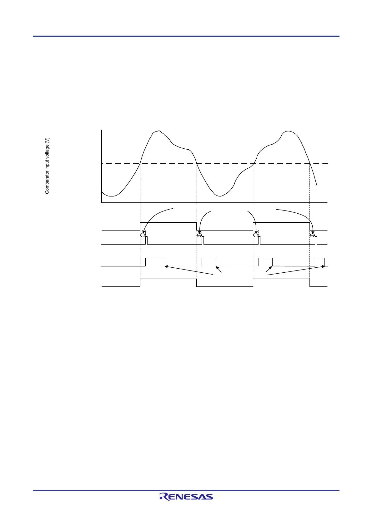
Figure 14-10 shows a comparator operation example. The VCOUT0 output becomes 1 when the analog input voltage is
higher than the comparator input voltage voltage, and the VCOUT0 output becomes 0 when the analog input voltage is
lower than the reference voltage. When the comparator output changes, an interrupt request and an ELC event are output.
Figure 14-10. Comparator Operation Example
(A) (B) (A) (B)
(A) (B) (A)
(B)
Set to 0 by software
“1”
“0”
“1”
“0”
“1”
“0”
ELC event output
Comparator interrupt
request output
CMPIF0 bit in interrupt
control register
VCOUT output
After VCOUT0 output, an interrupt request generated with a
delay of 3 operation clock cycles.
Reference input
voltage
(external reference
voltage or D/A
converter output
voltage)
Caution The above diagram applies when CPOE = 1 (pin output enabled), CDFS1 and CDFS0 = 00B (filter not
used), and CEGP = CEGN = 1 (both-edge selection). When CINV = 0, CEGP = 1, and CEGN = 0 (rising-
edge selection for non-inversion output signal from the comparator), CMPIF0 changes as shown by
(A) only. When CINV = 0, CEGP = 0, and CEGN = 1 (falling-edge selection for non-inversion output
signal from the comparator), CMPIF0 changes as shown by (B) only. When CPOE = 1, VCOUT0 directly
outputs the ELC event output.
 Loading...


