RL78/F13, F14 CHAPTER 7 TIMER RJ
R01UH0368EJ0210 Rev.2.10 547
Dec 10, 2015
7.3.2 Operation speed mode control register (OSMC)
The low-speed on-chip oscillator can be operated by setting the WUTMMCK0 bit in the OSMC register.
To select the low-speed on-chip oscillator as the count source of the timer RJ, set the bits TCK2 to TCK0 in the timer RJ
mode register 0 (TRJMR0).
The RTCLPC bit is used to reduce power consumption by stopping unnecessary clock functions.
For the setting of the RTCLPC bit, see CHAPTER 5 CLOCK GENERATOR.
Set the OSMC register by an 8-bit memory manipulation instruction.
Reset signal generation clears this register to 00H.
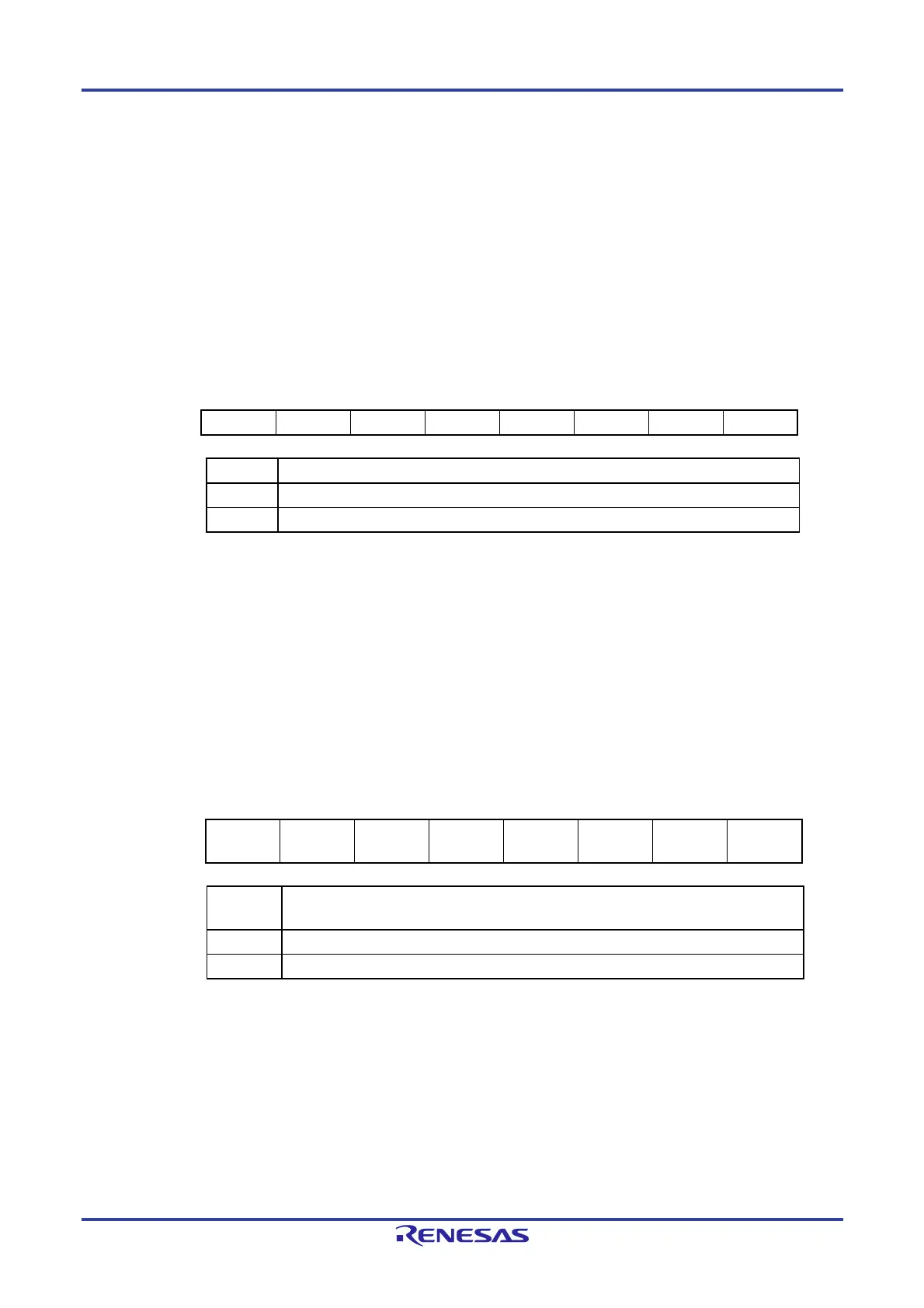
Figure 7-3. Format of Operation Speed Mode Control Register (OSMC)
Address: F00F3H After reset: 00H R/W
Symbol 7 6 5 4 3 2 1 0
OSMC RTCLPC 0 0
WUTMMCK0
0 0 0 0
WUTMMCK0
Low-speed on-chip oscillator operation control
0
Low-speed on-chip oscillator operating
1
Low-speed on-chip oscillator stopped
7.3.3 Clock Select Register (CKSEL)
This register is used to select the CPU clock (f
SUB/fIL) the clocks for the timer RJ, timer RD, and clock output/buzzer
output. Together with the CMC register, the SELLOSC bit is used to set the operation mode of the subsystem clock.
For details, see Figure 5-3 Format of Clock Operation Mode Control Register (CMC).
Set the CKSEL register by a 1-bit or 8-bit memory manipulation instruction.
Writing to the CKSEL register is disabled when the GCSC bit of the IAWCTL register is set to 1.
Figure 7-4. Format of Clock Select Register (CKSEL)
Address: F02C4H After reset: 00H R/W
Symbol 7 6 5 4 3 <2> 1 <0>
CKSEL 0 0
0 0
0
TRD_CKS
EL
0
SELLOSC
Notes 3, 4
SELLOSC
Notes 3, 4
Control of sub/low-speed on-chip oscillator selection clock (f
SL) selection
0 Selects fSUB
Note 1
1 Selects fIL
Note 2
Notes 1. When setting f
SUB as the CPU/peripheral hardware clock, first set the SELLOSC bit to 0 and
then set the CSS bit in the CKC register to 1.
2. When setting f
IL as the CPU/peripheral hardware clock, first set the SELLOSC bit to 1 and
then set the CSS bit in the CKC register to 1.
3. When the SELLOSC bit is set to 1, the low-speed on-chip oscillator operates.
4. When setting the CKSEL register in the 20-, 30-, or 32-pin products, set the SELLOSC bit to
1.

 Loading...


