RL78/F13, F14 CHAPTER 22 KEY INTERRUPT FUNCTION
R01UH0368EJ0210 Rev.2.10 1517
Dec 10, 2015
22.3 Register Controlling Key Interrupt
22.3.1 Key return mode register (KRM)
The KRM0 to KRM7 bits control signals KR0 to KR7.
The KRM register can be set by a 1-bit or 8-bit memory manipulation instruction.
Reset signal generation clears this register to 00H.
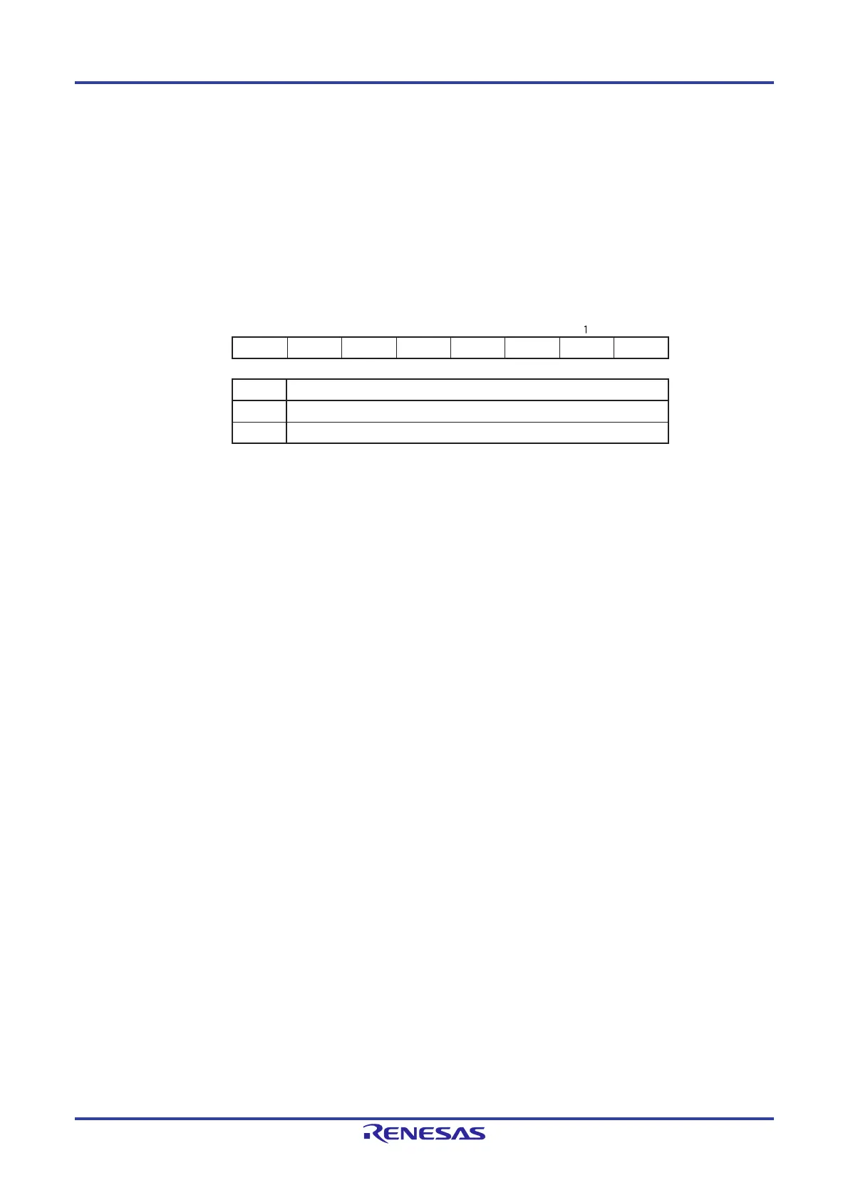
Figure 22-2. Format of Key Return Mode Register (KRM)
Cautions 1. An interrupt will be generated if the target bit of the KRM register is set to 1 while the KRn pin is
at low level. To ignore this interrupt, set the KRM register after disabling interrupt servicing by
using the interrupt mask flag. Afterward, clear the interrupt request flag after waiting for the key
interrupt input low-level width (tKR).
2. The pins not used in the key interrupt can be used as normal ports.
3. When the assignment of the key interrupt input pin is changed by using the PIOR50 bit, an
interrupt may be generated. The pin assignment must be changed while the KRM register is 00H
or while the key input interrupt is prohibited.
4. Set the bits of the KRM register to 0 for pins to which the key interrupt function is not to be
allocated.
Remark n = 0 to 7
KRM7
Does not detect key interrupt signal
Detects key interrupt signal
KRMn
0
1
Key interrupt mode control
KRM KRM6 KRM5 KRM4 KRM3 KRM2 KRM1
KRM0
Address: FFF37H After reset: 00H R/W
Symbol
765432 0
 Loading...


